Imaging system and methods for cardiac analysis

a cardiac analysis and imaging system technology, applied in the field of 3d imaging systems, can solve the problems of difficult diagnosis of stenosis or other abnormalities, difficult to detect coronary calcification and measurable, and provide an efficient or intuitive means to analyze complex organs, etc., to reduce visual clutter, efficient and accurate detection and view, and less problematic scoring of coronary plaques

Inactive Publication Date: 2011-08-25
VIATRONIX
View PDF2 Cites 127 Cited by
  • Summary
  • Abstract
  • Description
  • Claims
  • Application Information

AI Technical Summary

Benefits of technology

[0011]The present invention relates to imaging systems and methods for viewing medical to images of human anatomy and, in particular, to a 3-dimensional imaging system that allows a user to efficiently and accurately detect and view coronary artery calcification as displayed graphically on a computer screen. Systems and methods are provided that help make the scoring of coronary plaques less problematic. For example, a method according to one aspect of the invention provides automated differentiation of noise and bones based on user-specified volume thresholds to reduce visual clutter and allow a less tedious method of selecting lesions (plaques). In another aspect, a method is provided for using an integrated 3D shaded surface display with overlaid plaques, which more clearly shows the distribution of plaques, for better visualization.

Problems solved by technology

However, while stacks of such slices may be useful for analysis, they do not provide an efficient or intuitive means to analyze complex organs such as the heart, or other organs as tortuous and complex as the colon or arteries.
For example, when imaging blood vessels, cross-sections merely show slices through vessels, making it difficult to diagnose stenosis or other abnormalities.
Unfortunately, coronary calcification is not easily detected and measurable with conventional chest radiographs and other conventional systems and methods.

Method used


Image

  • Imaging system and methods for cardiac analysis
  • Imaging system and methods for cardiac analysis
  • Imaging system and methods for cardiac analysis

Examples


Embodiment Construction

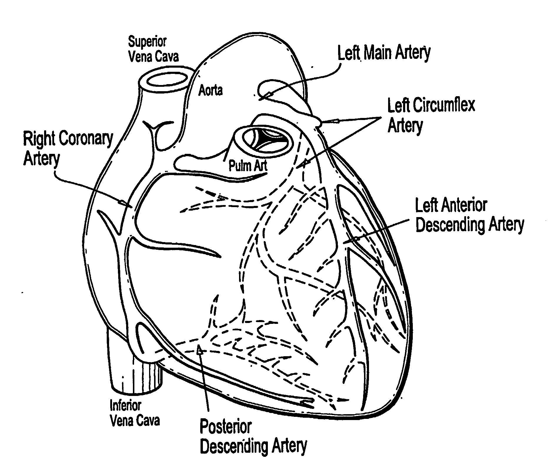
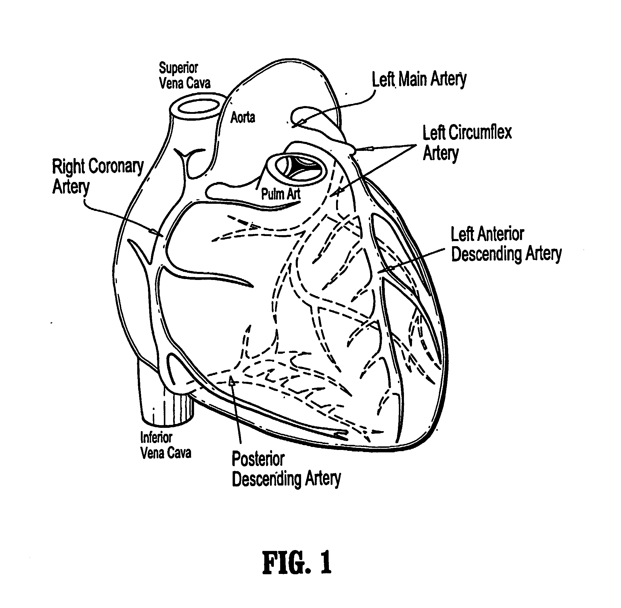
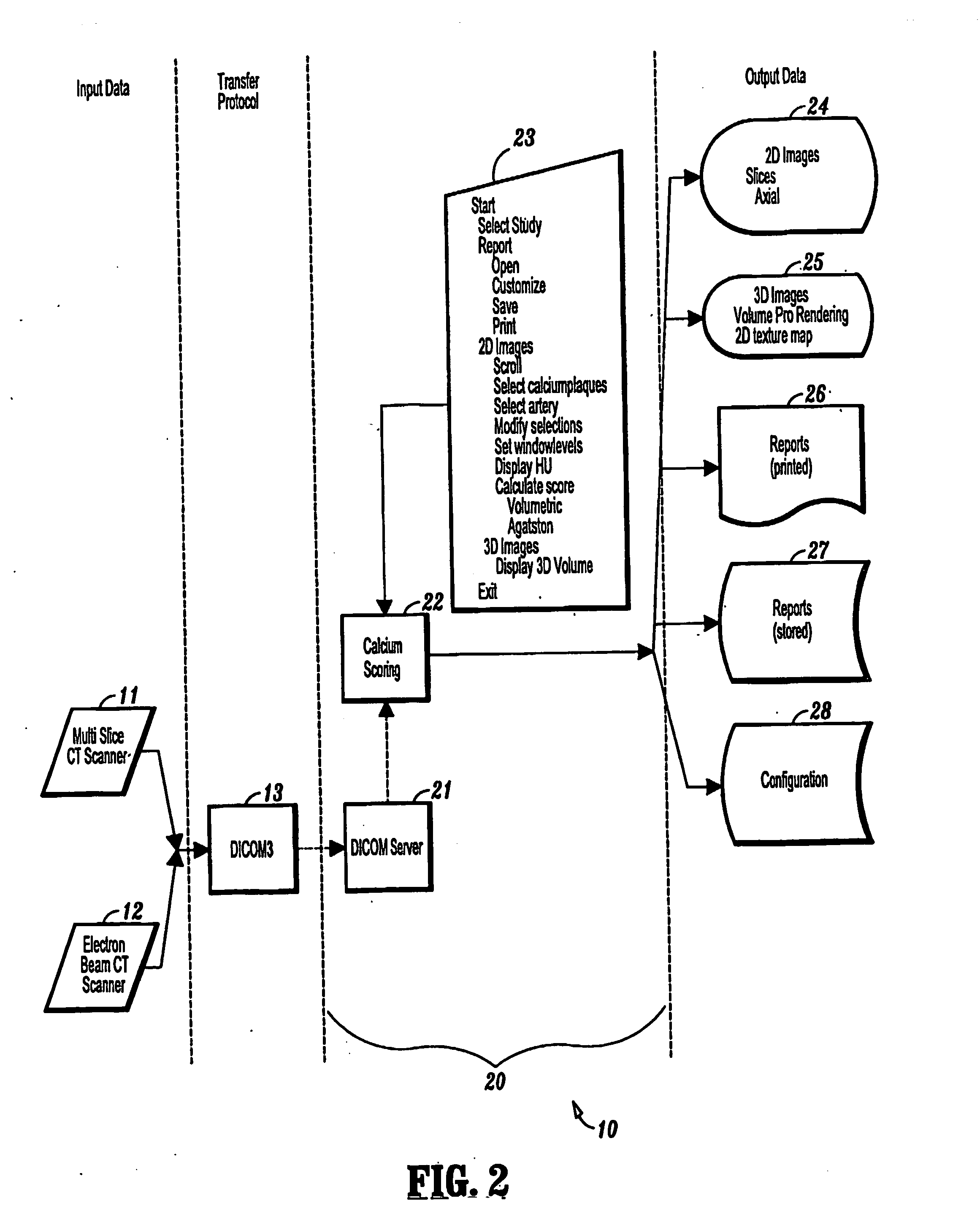
[0025]The present invention is generally directed to imaging systems and methods for viewing medical images of human anatomy. Preferred embodiments of the invention are directed to 3D imaging systems comprising a calcium scoring tool that can be used by physicians for cardiac analysis and determining the amount of calcium plaque accumulation in coronary arteries, although one of ordinary skill in the art can readily envision application of the invention for diagnosing other anatomical components. A calcium scoring application according to the invention is preferably designed to receive a 2D image dataset from an Electron-Beam Computed Tomography (EBCT) or Multi-Slice Computed Tomography (MSCT) and transform the dataset into a 3D, density-filled electronic model of the patient's heart, which is displayed on a PC screen. In general, a calcium scoring application according to the invention enables physicians to (i) conduct a safe and effective calcium scoring examination of the electro...


PUM


Abstract

Imaging systems and methods for viewing medical images of human anatomy and, in particular, to a 3-dimensional imaging system that allows a user to efficiently and accurately detect and view coronary artery calcification as displayed graphically on a computer screen. In one aspect, a method for displaying medical images comprises obtaining an image dataset comprising anatomical image data (step 50), automatically grouping connected components in the image data to form groups of connected components (steps 50-57), and displaying the groups of connected components are distinguishable in the displayed image (58-59). The image dataset may comprise a volume data set and the groups of connected components comprise regions of neighboring voxels that share a similar property. The image dataset may comprise a 2-dimensional data set and the groups of connected components comprise regions of neighboring pixels that share a similar property. Different groups of connected components may be displayed in different colors and / or different opacities or certain groups may not be displayed at all.

Description

CROSS-REFERENCE TO RELATED APPLICATIONS[0001]This application claims priority to U.S. Provisional Application Nos. 60 / 331,799 and, 60 / 331,779, both of which were filed on Nov. 21, 2001, and both of which are fully incorporated herein by reference.TECHNICAL FIELD OF THE INVENTION[0002]The present invention relates generally to imaging systems and methods for viewing medical images of human anatomy. More specifically, the invention relates to a 3-dimensional imaging system that allows a user to efficiently and accurately detect and view coronary artery calcification as displayed graphically on a computer screen.BACKGROUND[0003]Various systems and methods have been developed to enable two-dimensional (2D) visualization of human organs, such as the heart, by radiologists and physicians for diagnosis and formulation of treatment strategies. Such systems and methods include CT (Computed Tomography) such as EBCT (Electron-Beam Computed Tomography) and MSCT (Multi-Slice Computed Tomography)...

Claims


Application Information

Patent Timeline
Patent Type & Authority Applications(United States)
IPC IPC(8): G06K9/00
CPCG06T11/001G06T7/0081G06T2207/30101G06T2207/30048G06T2207/20141G06T7/11G06T7/187
Inventor DACHILLE, FRANK C.KREEGER, KEVINHIZVER, JENNYCAI, WENLIECONOMOS, GEORGE
Owner VIATRONIX
Why Eureka
Try Eureka