
Fuel cell stack discrete header

a header and fuel cell technology, applied in the direction of fuel cells, fuel cell details, electrical equipment, etc., can solve the problems of inefficient use of plates and gaskets, differences in reactant and coolant flow rates into individual cells, and particular plate designs are limited to a relatively narrow range, so as to minimize the use of plates and gasket materials.

Inactive Publication Date: 2011-08-25
GM GLOBAL TECH OPERATIONS LLC
View PDF6 Cites 41 Cited by
  • Summary
  • Abstract
  • Description
  • Claims
  • Application Information

AI Technical Summary

Benefits of technology

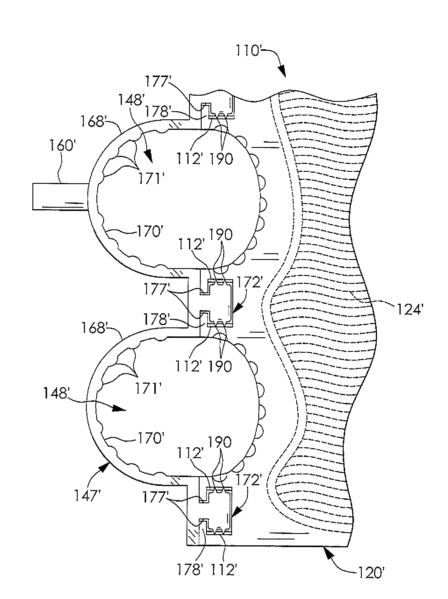
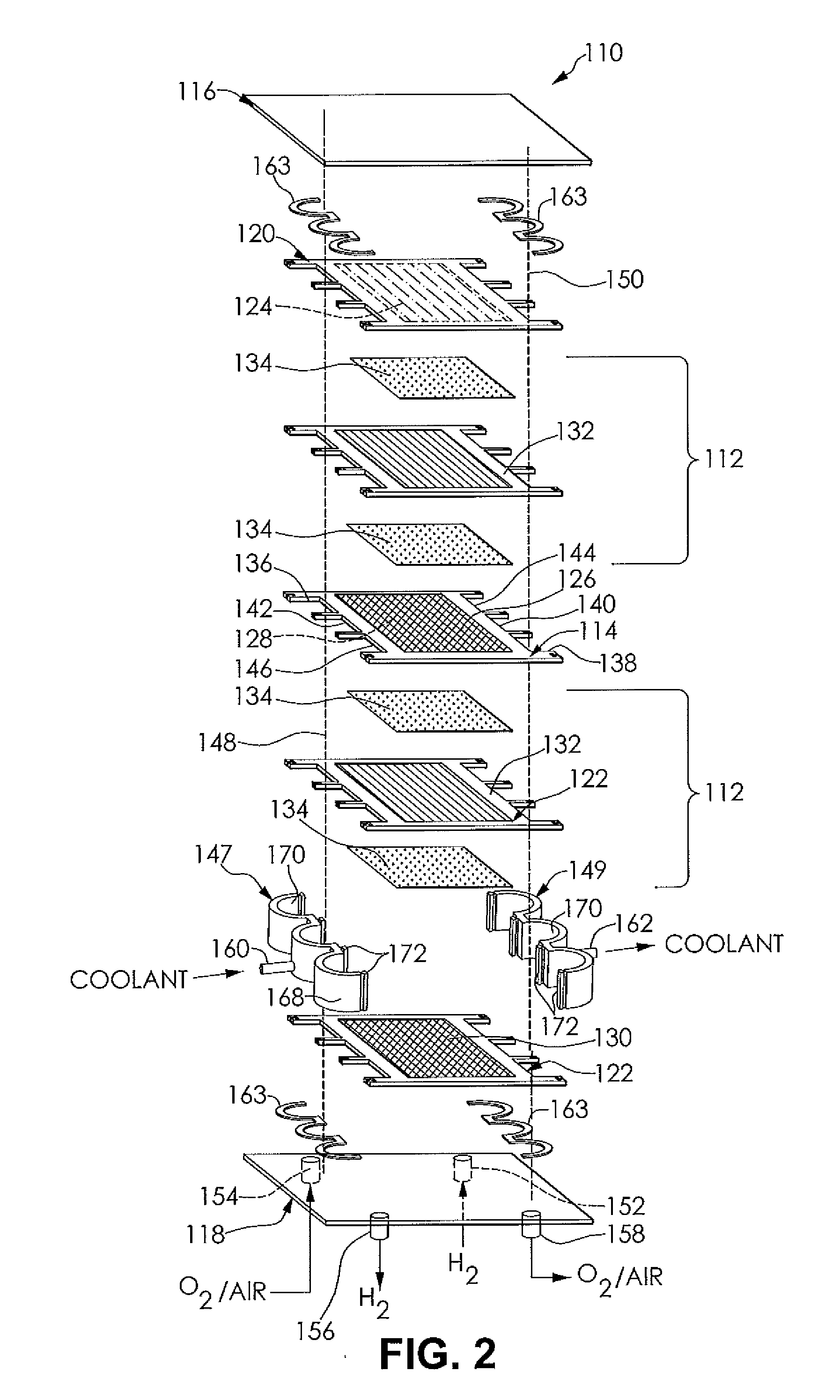
[0011]Presently provided by the invention, a discrete header for a fuel cell system that minimizes use of the plate and the gasket materials, allows a single plate design to be used for multiple fuel cell stack lengths having a large differential of energy requirements, provides a durable alignment mechanism for the fuel cell stack, and provides integration flexibility for components and configurations of the fuel cell system, has surprisingly been discovered.

Problems solved by technology

Large areas of inactive areas on plates result in an inefficient use of the plate and a gasket used to form the individual cells.
As a result, a particular plate design is limited to a relatively narrow range of stack lengths, and a manufacturer may be required to support multiple plate designs to accommodate a number of vehicles having a large differential of energy requirements.
A consistent cross sectional shape may be undesirable for to the fuel cell stack because a pressure differential may exist along the length of the header, causing differences in reactant and coolant flow rates into individual cells.
Additionally, plate formed headers limit header access to ends of the fuel cell stack for placement of components such as a distribution manifold, a water separator, and an infector, for example, necessary for operation of the fuel cell stack.

Method used


Image

  • Fuel cell stack discrete header
  • Fuel cell stack discrete header
  • Fuel cell stack discrete header

Examples


Embodiment Construction

[0024]The following detailed description and appended drawings describe and illustrate various embodiments of the invention. The description and drawings serve to enable one skilled in the art to make and use the invention, and are not intended to limit the scope of the invention in any manner.

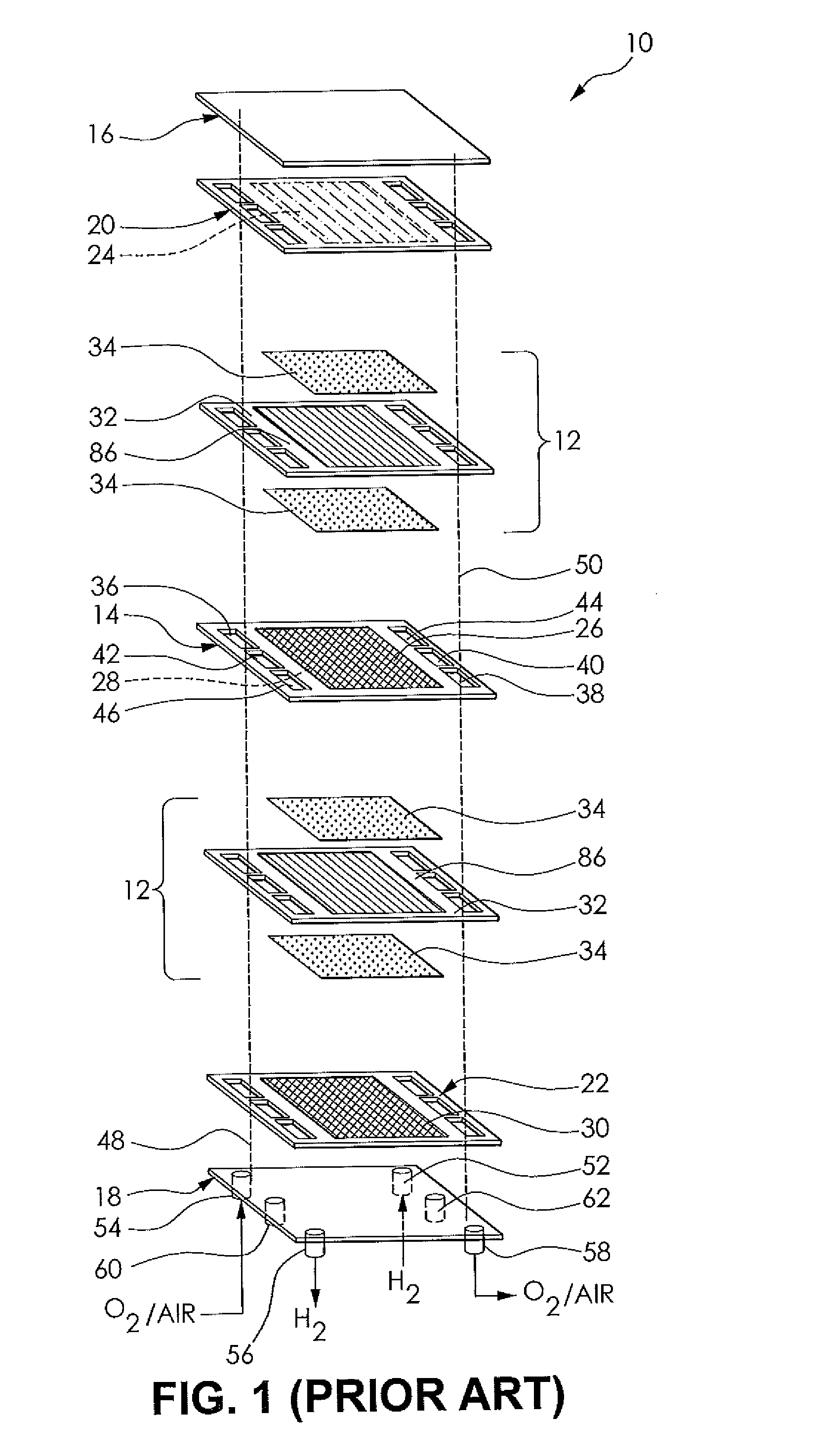
[0025]FIG. 1 depicts a fuel cell stack 10 having a pair of membrane electrode assemblies 12 separated from each other by an electrically conductive bipolar plate 14. For simplicity, only a two-cell stack (i.e. one bipolar plate) is illustrated and described in FIG. 1, it being understood that the fuel cell stack 10 will typically have many more cells and bipolar plates.

[0026]The membrane electrode assemblies 12 and bipolar plate 14 are stacked together between a pair of clamping plates 16, 18 and a pair of unipolar end plates 20, 22. The clamping plates 16, 18 are electrically insulated from the end plates 20, 22 by a seal or a dielectric coating (not shown). The unipolar end plate 20, both wo...


PUM

PropertyMeasurementUnit
lengthaaaaaaaaaa
non-conductiveaaaaaaaaaa
hydrophilicaaaaaaaaaa

Abstract

A fuel cell system comprises a main body including a first partial header and a fastening point. The main body is adapted to be coupled to a plurality of plates forming a fuel cell stack, allowing a single plate design to be used for multiple fuel cell stack lengths having a large differential of energy requirements, affording a durable alignment mechanism for the fuel cell stack, and providing integration flexibility for components and configurations of the fuel cell system.

Description

FIELD OF THE INVENTION[0001]The present disclosure relates to a fuel cell assembly and more particularly to header manifolds for reactants and coolant supplied to and removed from a fuel cell stack.BACKGROUND OF THE INVENTION[0002]Fuel cell systems are increasingly being used as a power source in a wide variety of applications. Fuel cell systems have been proposed for use in power consumers such as vehicles as a replacement for internal combustion engines, for example. Such a system is disclosed in commonly owned U.S. patent application Ser. No. 10 / 418,536, hereby incorporated herein by reference in its entirety. Fuel cells may also be used as stationary electric power plants in buildings and residences, as portable power in video cameras, computers, and the like. Typically, the fuel cells generate electricity used to charge batteries or to provide power for an electric motor.[0003]Fuel cells are electrochemical devices which combine a fuel such as hydrogen and an oxidant such as ox...

Claims


Application Information

Patent Timeline
Patent Type & Authority Applications(United States)
IPC IPC(8): H01M8/02H01M50/77
CPCH01M8/0247H01M8/0267H01M8/0273H01M8/04753H01M8/04074H01M8/04089H01M8/04701Y02E60/50H01M8/2483H01M8/242H01M8/2485H01M8/0271H01M8/2484H01M8/0297
Inventor BOGUMIL, TODD D.SKALA, GLENN W.BEUTEL, MATTHEW J.
Owner GM GLOBAL TECH OPERATIONS LLC
Learn More