
Snowplowable pavement marker

Inactive Publication Date: 2002-08-27
LOWE HARRY E
View PDF16 Cites 11 Cited by
  • Summary
  • Abstract
  • Description
  • Claims
  • Application Information

AI Technical Summary

Benefits of technology

to provide a pavement marker that is resistant to damage from snowplow blades and protects the retroreflector;
to provide a pavement marker that is easily installed, using conventional equipment and techniques;
to provide a pavement marker that has the reflector carrying web between the ramps initially below the pavement surface so as to reduce snowplow blade impact while allowing openess to oncoming light;
to provide a pavement marker that minimizes use of installation adhesive, as well as minimizing unsightly overflow of adhesive; and
to provide a pavement marker whereby rail height is reduced by allocating structural integrity responsibility to nearby structures.
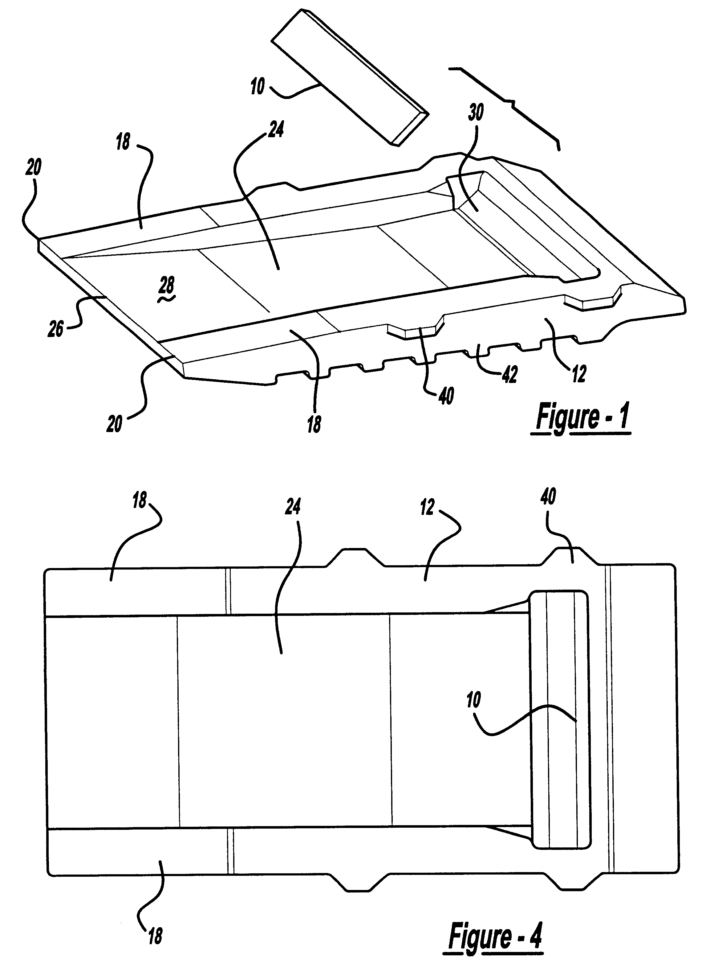
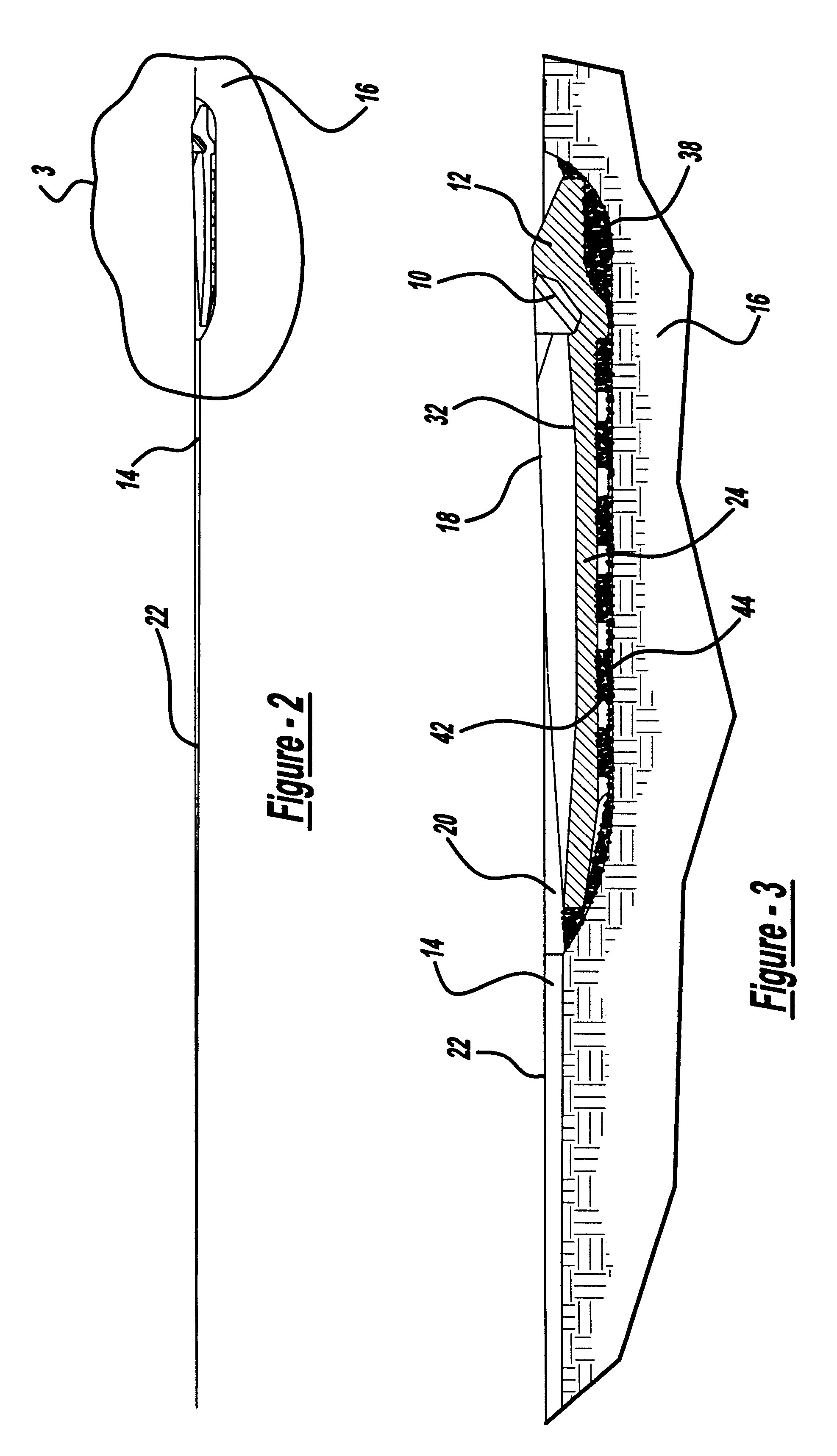
The pavement marker includes a base member with two longitudinally extending and laterally spaced apart ramps. The ramps are designed to start at a level below pavement and extend above the pavement level to help guide the snowplow blade up and over the retroreflector. The bottom side of the reflector base has a series of cleats or treads on either side to help anchor the base into a prepared roadway through the use of epoxy. The cleats help prevent dislocation of the pavement marker base relative to the roadway. Positioning tabs can be included on either side of the pavement marker base to align the marker relative to the surrounding pavement. The retroflector is carried in a pocket on the web which preferably spans the ramps along their entire length. The proper placement of the marker will put the retroreflector starting at a level below the pavement extending to a level above the surrounding pavement, but still protected by the ramps of the pavement marker base from the snowplow blade. The reflector will be exposed to light from both above pavement level and light traveling down the cut groove.

Problems solved by technology

The markers are designed to accommodate the action of snowplow blades which can be a major source of damage to the pavement marker and its reflective element.
Damage occurs because the snowplow blade is traveling at approximately traffic speeds and contacts the portion of the pavement marker above the pavement level.
Snowplows may also damage the pavement markers by having the leading tip of the blade enter the marker at such a point that the blade is not guided over the marker, but rather impacts the reflector directly.
In these prior art designs it is recognized that there was a continuing problem to reduce the overall height of the reflector of the pavement marker to a minimum level above the roadway while still maintaining the reflector above the roadway surface.
Working against this goal, however, was the recognition that the higher the pavement marker was above the roadway, the more of an obstacle it presented to an oncoming snowplow, and the greater damage it would receive from impact with the snowplow.
While providing snowplow protection, this installation has had limited use for a variety of reasons, including the filling of the groove with road debris such as dirt, sand, eroded pavement, and the fact that the reflector was below pavement level served to limit the reflective light to the motorist.

Method used


Image

  • Snowplowable pavement marker
  • Snowplowable pavement marker
  • Snowplowable pavement marker

Examples


Embodiment Construction

The present invention has a reflector 10 mounted in a base 12 to reflect light from the headlamps of a vehicle back to the driver of the vehicle. Reflector or retroreflector as used herein can be a plastic, glass or composite material designed to reflect the light from oncoming headlamps back to the driver. Prior art metallized lens can also be used. For examples of reflectors, see Balint, U.S. Pat. No. 3,409,344 which discloses acrylic lens elements in an ABS housing. Another example of a retroreflector element is shown in Flanagan, U.S. Pat. No. 4,498,733. Various models of reflectors known to those in the art can be used such as Stimsonite Model 944 retroreflector, available in the trade or 3M model #194 of retroreflector.

As shown in FIG. 2, the present marker is designed to be placed in a groove 14 cut in the pavement 16. The groove is several times the length of the marker. The length of the groove is determined in part by the need for light to travel in the groove to impinge o...


PUM


Abstract

A very low-profile snowplowable pavement marker mounted in an elongated groove formed in a highway pavement, the groove extending longitudinally of the highway and exposing the reflective highway marker to the headlights of oncoming motor vehicles when their approach distance from the reflective highway marker is adequate for highway guidance purposes. The reflective highway marker is a metal casting with a reflector mounted in a pocket formed in the casting. The casting is adhesively installed in a deepened section of the groove. The protective rails of the casting are situated slightly above the pavement surface, but are significantly lower than rails of prior art snowplowable castings. The leading edge of the reflector support is below pavement level and allows light from oncoming headlights to enter the reflector without the shadowing effect prevalent in conventional low-profile marker castings. The elongated groove is much shallower and longer than grooves of prior art, and allows for car tires to enter and clean the reflector in the casting.

Description

The present invention relates to pavement markers which are recessed into the pavement surface. The pavement marker is designed for use in areas that receive snowfall and hence, is designed to be snowplowable while resistant to damage from the action of the snowplow.SUMMARY OF THE PRIOR ARTPavement markers, as used herein, are mechanisms for setting a reflective element in or on the roadbed so that the light of the vehicle headlamps can be reflected back to the driver. The source of the reflection delineates edges of lanes, on / off ramps, and other features of the roadbed. These pavement markers are used in addition to, or instead of, standard paint, epoxy, or thermoplastic striping.Pavement markers are generally broken down into two types--sun country or snowplowable. Sun country markers are used where snow is either not present or an infrequent event, and thus their design does not have to take into account the operation of a snowplow to clear the traffic lanes. Snowplowable marker...

Claims


Application Information

Patent Timeline
IPC IPC(8): E01F9/04E01F9/06
CPCE01F9/06E01F9/553
Inventor LOWE, HARRY E.
Owner LOWE HARRY E
Learn More