
Flexible acl instrumentation, kit and method

a technology of flexible acl and kit, applied in the field of flexible acl and anterior cruciate ligament, can solve the problems of reduced rotational stability of acl replacement, difficult to hyperflex, and inability to allow surgeons to position guide pins

Active Publication Date: 2011-08-25
HOWMEDICA OSTEONICS CORP
View PDF101 Cites 94 Cited by
  • Summary
  • Abstract
  • Description
  • Claims
  • Application Information

AI Technical Summary

Benefits of technology

[0031]The step of directing the distal tip of the curved guide towards the surface of the bone may further include engaging the bone with the distal tip of the curved guide wherein the distal tip is pointed. This step may alternatively include engaging anatomy, such as soft tissue, overlying the bone, with the distal tip of the curved guide wherein the distal tip is a flange. The flange may further be adapted to match the anatomy of the soft tissue. Either of the pointed tip or flange configurations may provide a surgeon with assurance that the curved guide is in proper placement for the ACL repair.

Problems solved by technology

ACL injuries are often caused by a sudden force applied to the knee, and are a common form of injury in athletic activities.
The injury occurs typically when the knee is bent or twisted in an awkward direction.
However, this procedure often does not allow the surgeon to position the guide pin at the correct anatomical site of the native ACL on the femur.
As a result, the rotational stability of the ACL replacement is reduced.
The hyperflexion has various drawbacks: the surgeon loses the visual reference to anatomic landmarks that are usually seen at a normal, ninety degree, flexion, and hyperflexion is difficult to do when using a leg holder, which is typically used in all repair procedures, or may be impossible due to a patient's build or anatomy.
The surgeon can compromise tunnel integrity and thus fixation strength if the joint is not hyperflexed properly.
In order to maintain the joint volume free of these other substances, the clear liquid must be maintained at an elevated pressure, otherwise viewing ability is lost.
Typically in arthroscopic procedures, a surgeon will use a cannula, or the like, which provides an entryway for surgical tools into the joint, as well as, detrimentally, an exit for the clear liquid from the joint.
And in some instances, such a large amount of clear fluid is lost through the cannula or cannulated guide tool that maintaining the elevated pressure is not feasible.
Moreover, the clear fluid may exit onto the surgeon's hands and even the floor, leading to dangerous safety conditions such as a slippery floor where the surgeon is working.

Method used


Image

  • Flexible acl instrumentation, kit and method
  • Flexible acl instrumentation, kit and method
  • Flexible acl instrumentation, kit and method

Examples


Embodiment Construction

[0062]While the following instrumentation and surgical methods may be used to repair any suitable type of soft tissue—such as ligaments and tendons in a knee, hip, ankle, foot, shoulder, elbow, wrist, hand, spine, or any other area of anatomy—arthroscopic repairs of an ACL in a knee joint will be the exemplary focus of the disclosure below. In most of the below embodiments, the present invention forms a tibial bone tunnel and a femoral bone tunnel, each of which engages one end of an ACL replacement graft. The bone tunnels are intended to be positioned substantially at the location of the native ACL connection sites, though other locations may be used as desired or required based on the specific circumstances of a particular patient.

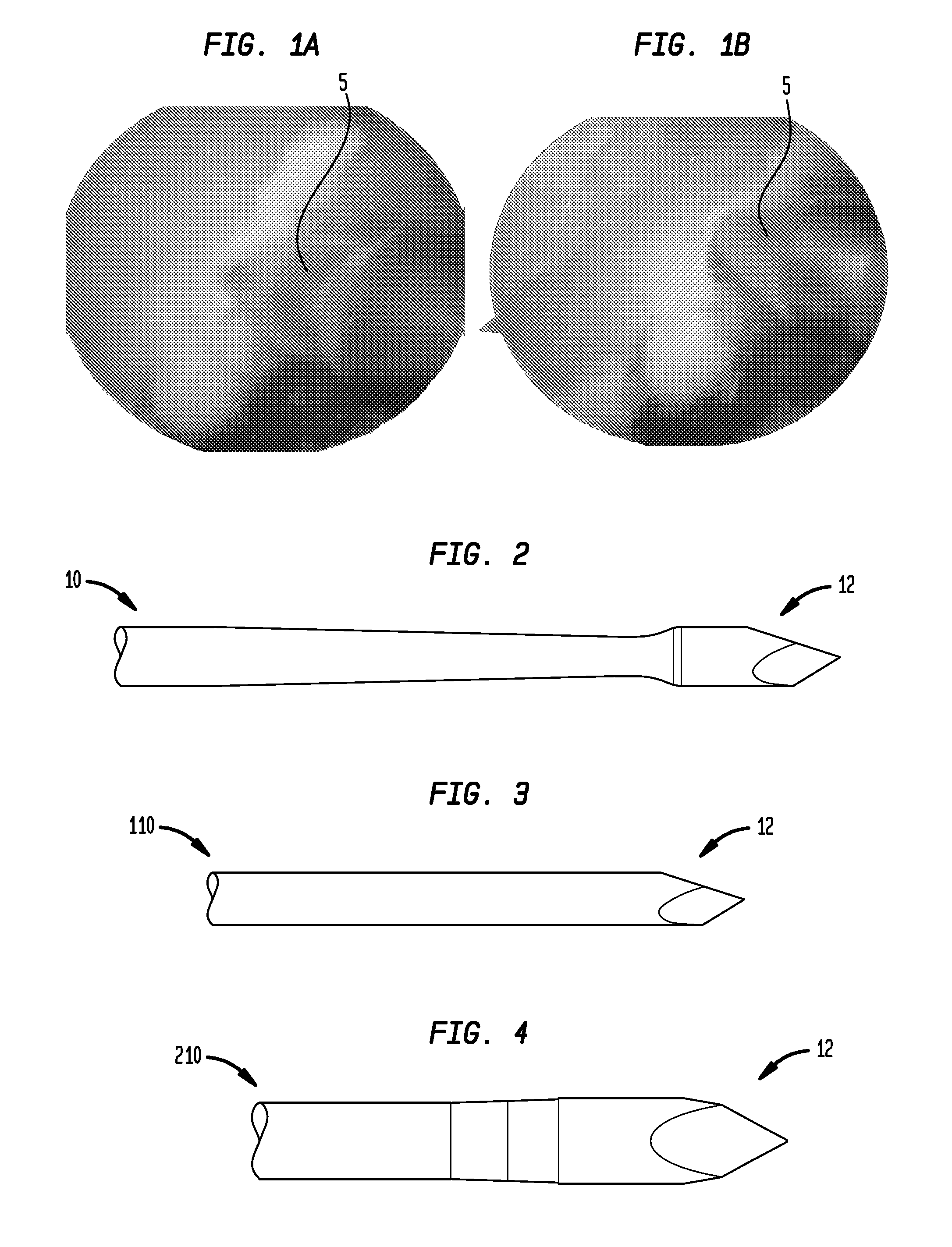
[0063]In a first embodiment, the instrumentation system may optionally include a starter awl 5 configured to create a pilot divot on the bone which will designate an anatomic insertion point. The awl, as illustrated in FIGS. 1A-B, may form a divot within...


PUM


Abstract

In a first embodiment, the present invention includes an instrumentation system for preparing a bone for soft tissue repair, the instrumentation system including a flexible drill pin capable of bending along a curved path; an aimer capable of engaging the flexible pin to bend the flexible pin; and a flexible reamer having a flexible portion along at least a portion of its length, the flexible portion comprising a plurality of laser cuts. In an alternate embodiment, the present invention may also include a method for preparing a bone tunnel in a femur adjacent a knee joint, the method including introducing a flexible drill pin into the knee joint; guiding the flexible drill pin towards a surface of the femur with an instrument introduced into the knee joint; drilling the flexible drill pin into the femur; removing the instrument from the knee joint; introducing a cannulated flexible reamer into the knee joint by placing the flexible pin within the cannulation of the flexible reamer; and reaming the bone tunnel in the femur along the path of the flexible pin.

Description

CROSS-REFERENCE TO RELATED APPLICATIONS[0001]This application claims the benefit of the filing date of U.S. Provisional Patent Application No. 61 / 274,690 filed Aug. 20, 2009, Provisional Patent Application No. 61 / 343,482 filed Apr. 29, 2010, and Provisional Patent Application No. 61 / 358,502 filed Jun. 25, 2010, the disclosures of which are hereby incorporated herein by reference.BACKGROUND OF THE INVENTION[0002]The present invention relates generally to instrumentation, kits and methods for repairing damage to soft tissue, including soft tissue such as tendons and ligaments, and particularly the anterior cruciate ligament (ACL) in the knee joint.[0003]ACL injuries are often caused by a sudden force applied to the knee, and are a common form of injury in athletic activities. The injury occurs typically when the knee is bent or twisted in an awkward direction.[0004]Current surgical repairs of ACL injuries may be arthroscopic or open and commonly include the formation of two bone tunne...

Claims


Application Information

Patent Timeline
Patent Type & Authority Applications(United States)
IPC IPC(8): A61B17/16
CPCA61B17/1615A61B17/1631A61B17/1637A61B17/1714A61B17/1764A61B17/1675
Inventor STEINER, MARKPILGERAM, KYLE CRAIGWEST, RAYMONDWYMAN, JEFFREYHEMSTREET, MATTHEWOREN, RANZAKAI, ERANRASH, ELAD
Owner HOWMEDICA OSTEONICS CORP
Learn More