
High-accuracy imep computational technique using a low-resolution encoder and a cubic spline integration process

a computational technique and low-resolution technology, applied in the direction of machines/engines, electrical control, instruments, etc., can solve the problems of computing power needed in electronic control units in order to process the large amount of crank position and cylinder pressure data for imep calculations, and achieve the effect of less computing resources for data processing and storag

Active Publication Date: 2011-08-25
GM GLOBAL TECH OPERATIONS LLC
View PDF8 Cites 3 Cited by
  • Summary
  • Abstract
  • Description
  • Claims
  • Application Information

AI Technical Summary

Benefits of technology

[0007]In accordance with the teachings of the present invention, a cubic spline integration method is disclosed for computing indicated mean effective pressure (IMEP) in an internal combustion engine using sparse input data. The cubic spline integration method requires significantly lower resolution crankshaft position and cylinder pressure input data than existing IMEP computation methods, while providing calculated IMEP output results which are very accurate in comparison to values computed by existing methods. By using sparse input data, the cubic spline integration method enables the use of a low-resolution crankshaft position encoder and requires less computing resources for data processing and storage.

Problems solved by technology

Requiring high-resolution crankshaft position and cylinder pressure data has a number of disadvantages, including the cost of the crank position encoder, the cost associated with the digital memory required to store the high-resolution cylinder pressure data over time, and the cost associated with computing power needed in electronic control units in order to process the large amounts of crank position and cylinder pressure data for IMEP calculations.

Method used


Image

  • High-accuracy imep computational technique using a low-resolution encoder and a cubic spline integration process
  • High-accuracy imep computational technique using a low-resolution encoder and a cubic spline integration process
  • High-accuracy imep computational technique using a low-resolution encoder and a cubic spline integration process

Examples


first embodiment

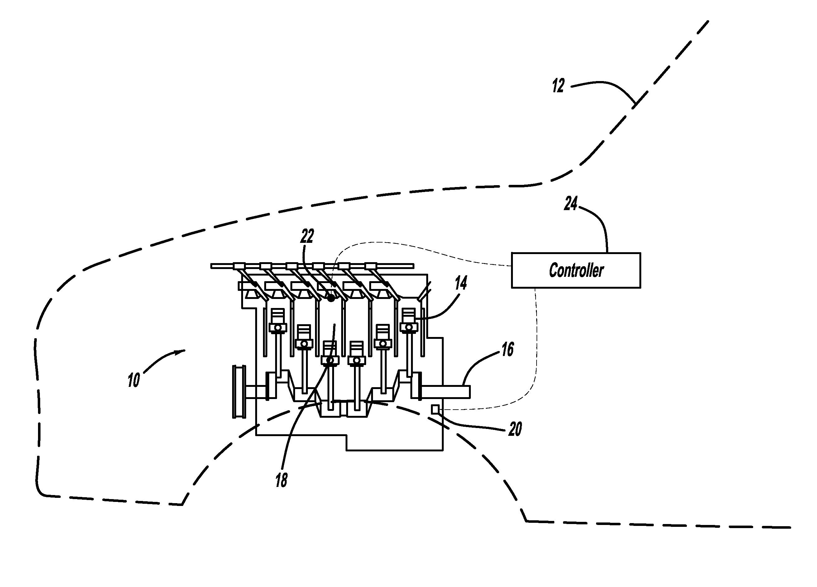
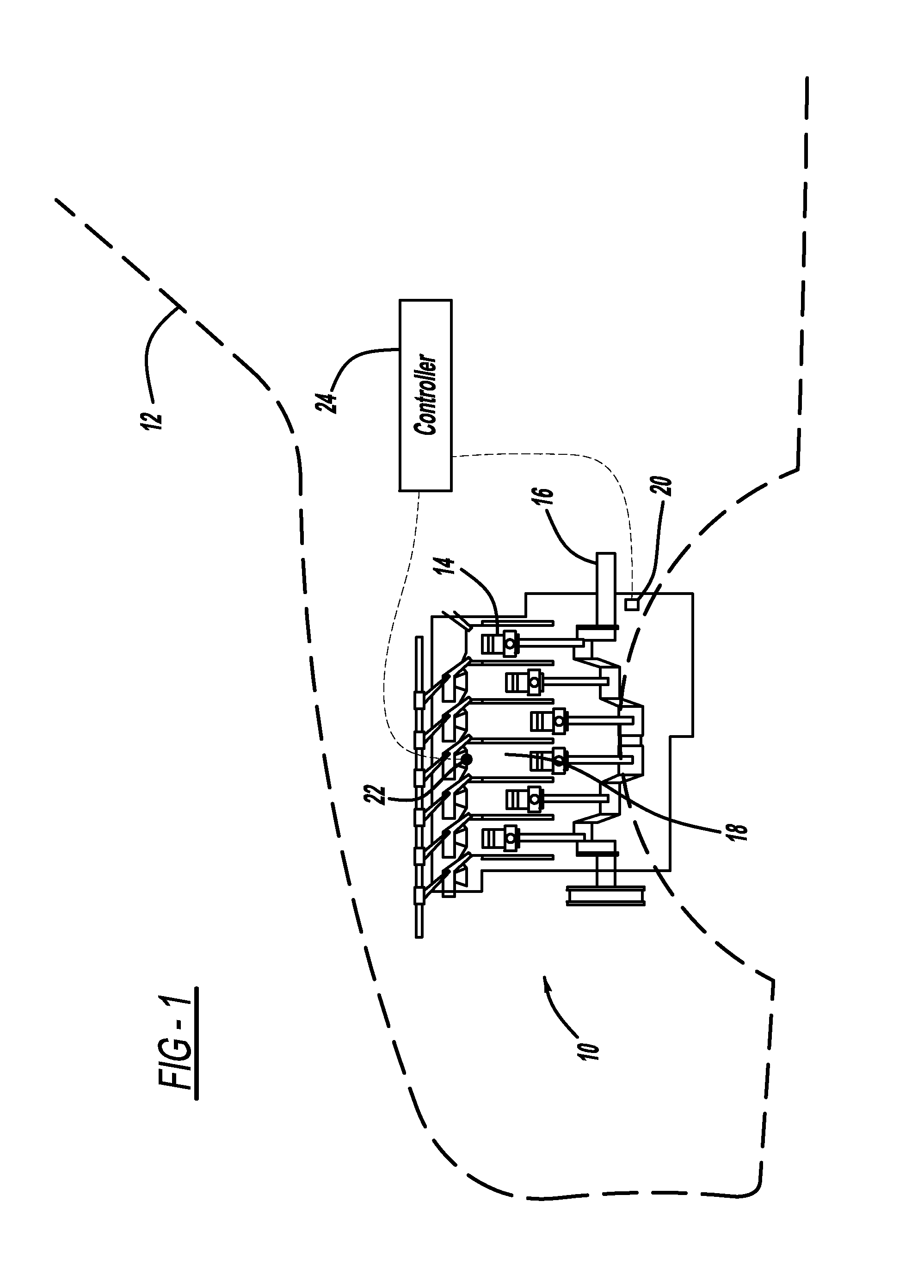
[0020]In the present invention, an indirect integration method of computing IMEP in an engine is provided. The indirect integration method begins with the introduction of a term PVn, where P is pressure, V is volume, and n is the ratio of specific heats. By definition,

d(PVn)=VndP+nVn−1PdV  (3)

and

d(PV)=VdP+PdV  (4)

[0021]Rearranging and integrating Equations (3) and (4) yields;

∫PV=1n-1·[∫1Vn-1·(PVn)-∫(PV)](5)

[0022]If the integral of Equation (5) is taken over a crank angle range from θ0 to θf, Equation (5) can be discretized and written as;

∫θ0θfPV≅1n-1·[1V_n-1·(PVn)θoθf-(PV)θoθf](6)

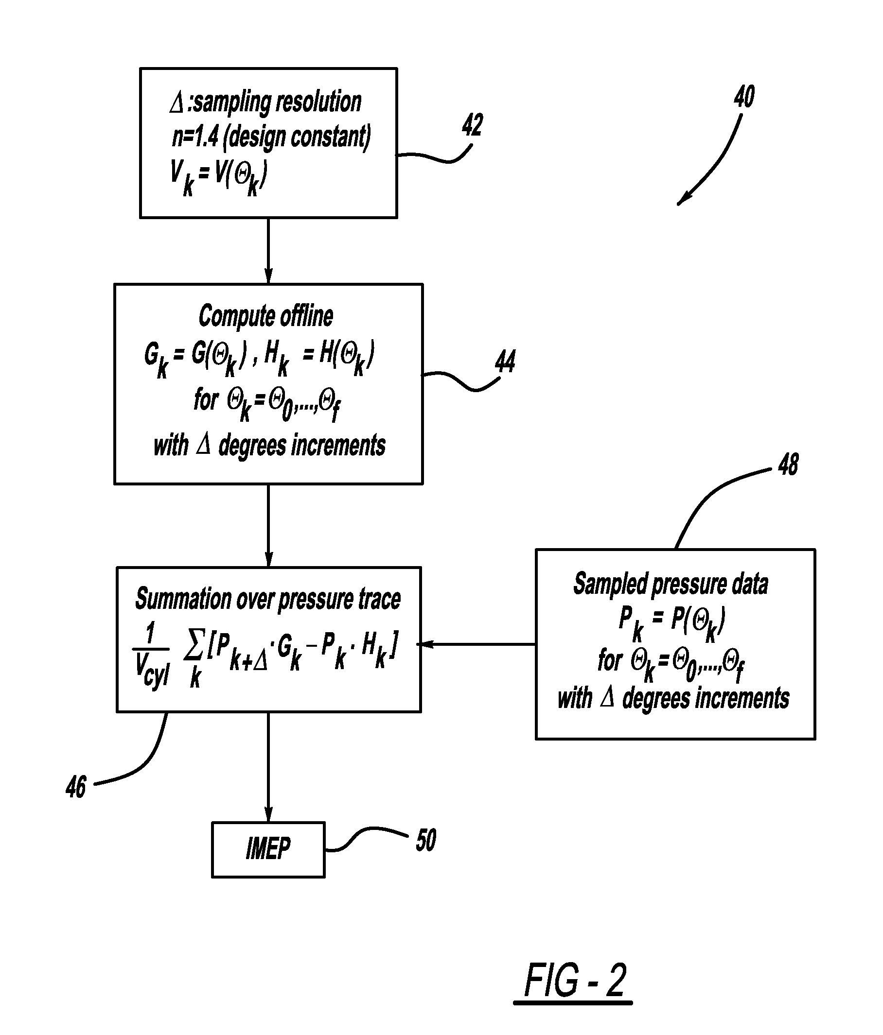
[0023]It can be seen that the left-hand side of Equation (6) is the definition of IMEP from Equation (1), with the exception that the (1 / Vcyl) factor is missing. It therefore follows that IMEP can be approximated as the right-hand side of Equation (6), multiplied by the (1 / Vcyl) factor, as follows;

IMEP≅1Vcyl·(n-1)·[1V_n-1·(PVn)θoθf-(PV)θoθf](7)

[0024]Equation (7) can then be expanded and written as a summati...

second embodiment

[0030]In the present invention, a cubic spline integration method of computing IMEP in an engine is provided. In the cubic spline integration method, a cubic spline is fitted to the integral Equation (1). This allows IMEP to be calculated with sufficient accuracy, even when using sparse cylinder pressure data. According to this method, f(x) is defined as a continuous function, as follows;

f(x)=1Vcyl·PVθ(12)

Where Vcyl is cylinder volume, P is cylinder pressure, and dV / dθ is the first derivative of cylinder volume with respect to crank angle position θ.

[0031]The function f(x) is defined to have a continuous third derivative through the interval [a, b], where;

a=x0<x1< . . . <xn−1<xn=b  (13)

[0032]It can be seen from Equation (1) and Equation (12) that a value for IMEP can be obtained by integrating the function f(x) over one power cycle, that is, from;

x0=180°·π180°to;(14)xn≅+179°·π280°(15)

[0033]Therefore an equation for IMEP can be written as;

IMEP=Sθf≅1Vcyl∫θoθfPV(16)

Where th...


PUM


Abstract

A method for computing indicated mean effective pressure (IMEP) in an internal combustion engine using sparse input data. The method uses a cubic spline integration approach, and requires significantly lower resolution crankshaft position and cylinder pressure input data than existing IMEP computation methods, while providing calculated IMEP output results which are very accurate in comparison to values computed by existing methods. By using sparse input data, the cubic spline integration method offers cost reduction opportunities for a manufacturer of vehicles, engines, and / or electronic control units, through the use of lower cost sensors and the consumption of less computing resources for data processing and storage.

Description

BACKGROUND OF THE INVENTION[0001]1. Field of the Invention[0002]This invention relates generally to a method for computing mean effective pressure in an engine and, more particularly, to a method for computing indicated mean effective pressure (IMEP) in an internal combustion engine using a cubic spline integration method which provides a highly accurate result even when using a low-resolution crankshaft position encoder and using less frequent measurement of cylinder pressure input data than required by existing IMEP calculation methods.[0003]2. Discussion of the Related Art[0004]Most modern internal combustion engines employ a number of sophisticated control strategies to optimize performance, fuel economy, emissions, and other factors. Among the many parameters used to control an engine's operation, indicated mean effective pressure (IMEP) is one of the more important. IMEP is used as a measure of the amount of work an engine is performing, or as a measure of the torque that is b...

Claims


Application Information

Patent Timeline
Patent Type & Authority Applications(United States)
IPC IPC(8): F02D45/00
CPCF02D35/023F02D2200/1004F02D2041/286F02D41/1497
Inventor JAVAHERIAN, HOSSEINHASKARA, IBRAHIMDAGCI, OGUZ H.
Owner GM GLOBAL TECH OPERATIONS LLC
Features
  • Generate Ideas
  • Intellectual Property
  • Life Sciences
  • Materials
  • Tech Scout
  • Unparalleled Data Quality
  • Higher Quality Content
  • 60% Fewer Hallucinations
Learn More