Sample receiving device

Active Publication Date: 2011-09-01
DNA GENOTEK
View PDF26 Cites 82 Cited by
  • Summary
  • Abstract
  • Description
  • Claims
  • Application Information

AI Technical Summary

Benefits of technology

[0013]In accordance with one aspect of the present invention, there is provided a sample receiving device for releasably storing a composition, comprising: (a) a lid comprising a reservoir for retaining said composition, and a pierceable barrier sealing said composition within said reservoir; and b) a funnel having a first open end for receiving a sample and a channel extending from said first open end to a second open end, said first open end configured for closure by said lid and said second open end being releasably or permanently attachable to a sample receptacle, wherein said funnel comprises one or more cutting ribs for cutting said pierceable barrier without a twisting action during closure of the lid.
[0014]In accordance with another aspect of the present invention, there is provided a sample receiving device for releasably storing a composition, comprising: a) a lid comprising a reservoir for holding a first substance, and a pierceable membrane sealing said first substance within said reservoir; b) a funnel having a first open end for receiving said sample and a channel extending from said first open end to a second open end, said first open end configured for closure by said lid and said second open end being releasably or permanently attachable to a sample rec

Problems solved by technology

A drawback of this container is that it includes multiple parts (e.g., lid, vial, disk, rod, rod holder), which increases the cost of manufacture of the container.
While the shape and size this container is well suited for collecting a biological sample from a donor, it does not lend itself well to high throughput analysis/testing or automation and is bulky/costly to transport.
Depending upon the nature of the substance released from the reservoir, the sponge may disintegrate and/or chemicals (e.g., adhesives) may be leached from the sponge and contaminate the sample.
Importantly

Method used


Image

  • Sample receiving device
  • Sample receiving device
  • Sample receiving device

Examples


Embodiment Construction

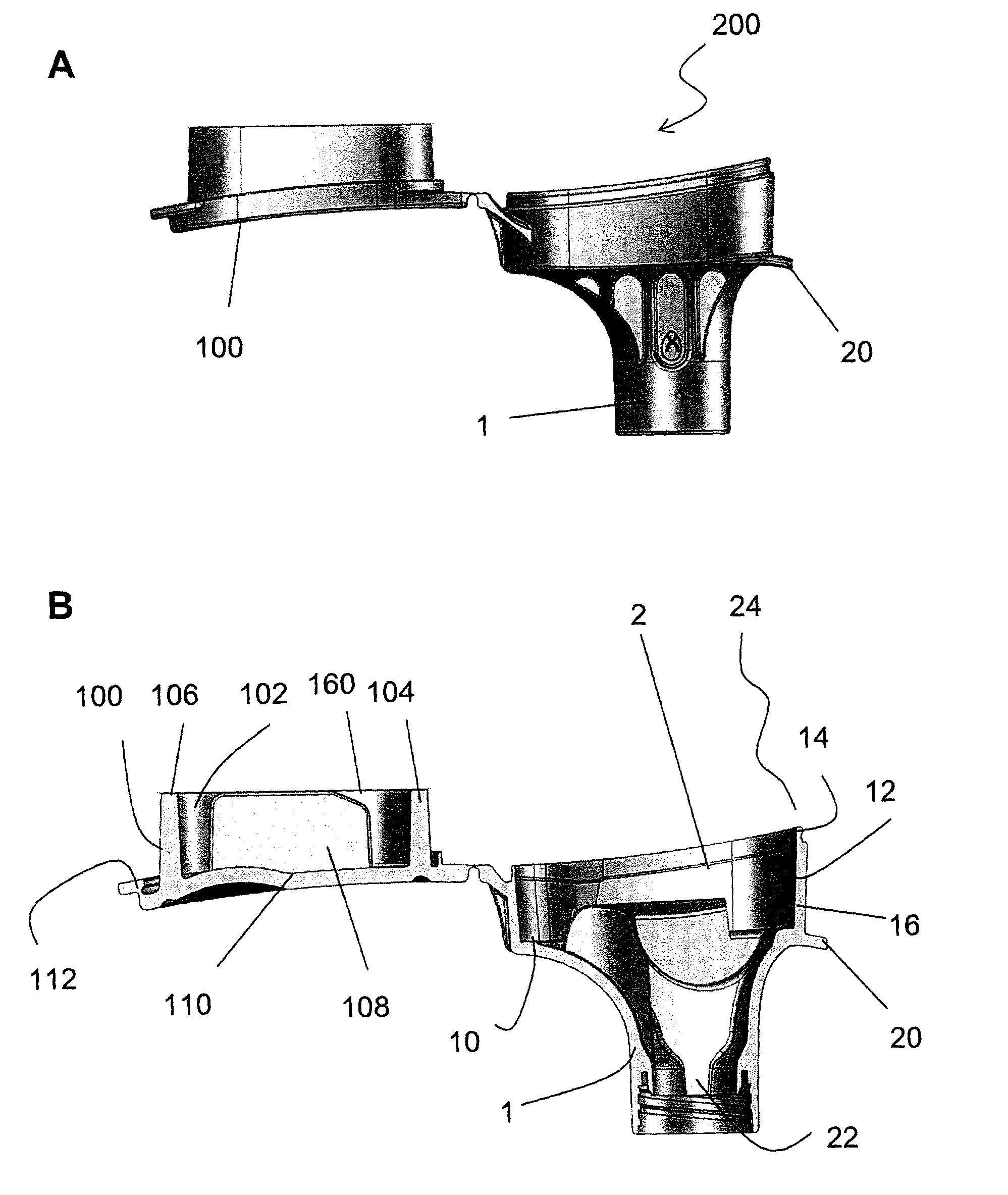
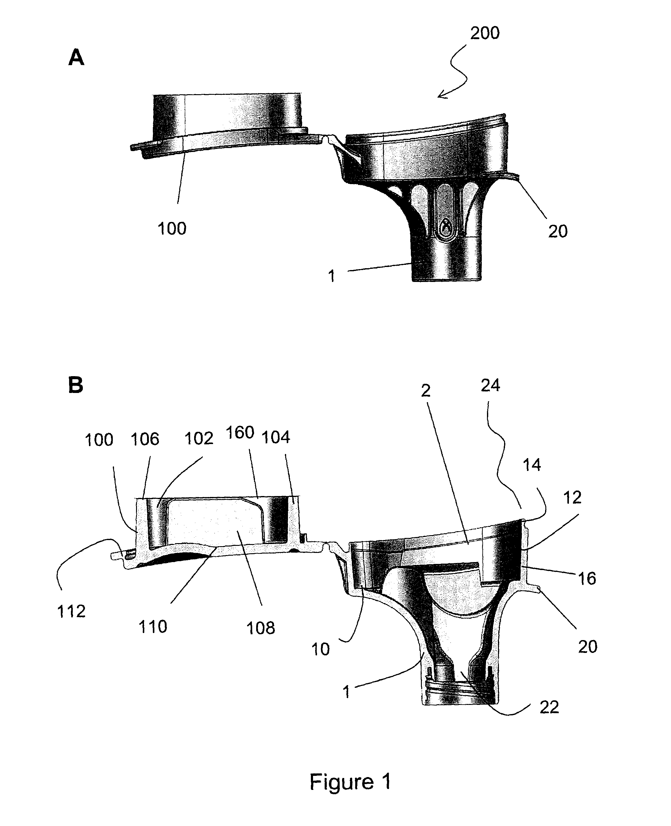
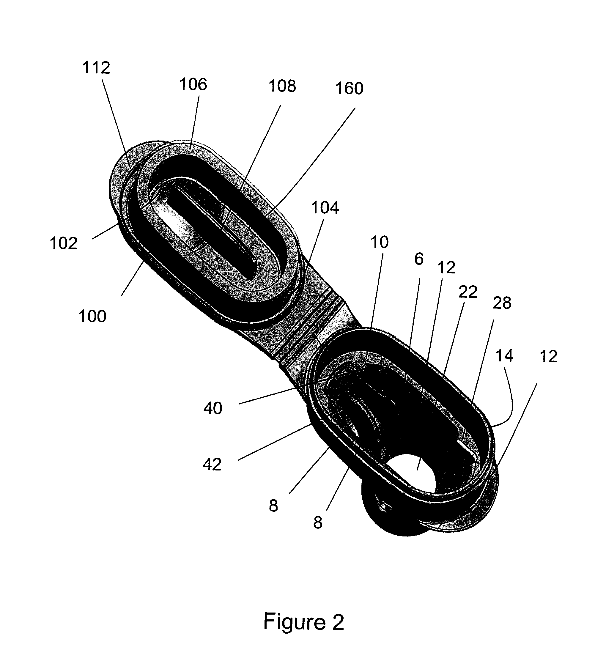
[0055]As will be discussed in more detail below, the present invention provides a sample receiving device designed to facilitate convenient sample collection and to maintain at least one substance, such as a preservative reagent, in a separate compartment for release into the sample following collection. The sample receiving device is further suitable for storing a concentrate / active ingredient separate from the substance stored in the lid, for example, as a dried mixture adhered to an inner surface of the lid, funnel and / or sample receptacle, such as a vial or tube, releasably or permanently attachable to the funnel.

[0056]The sample receiving device of the present invention has fewer component parts than are present in previously known sample receiving devices having a similar purpose. Thus, the device of the present invention can be less expensive and / or easier to manufacture and package, than such previous devices. Additionally, the manufacturing tolerances can be less precise fo...


PUM


Abstract

The present invention generally relates to a sample receiving device for releasably storing a substance. The sample receiving device includes a lid having a reservoir for retaining the substance, and a pierceable barrier sealing the substance within the reservoir; and b) a funnel for receiving a sample and configured for closure by the lid. The funnel is configured for releasable attachment to a sample receptacle such that a sample can be provided to the funnel and travel through the channel in the funnel into the sample receptacle. Further, the funnel includes one or more cutting ribs for cutting the pierceable barrier such that upon cutting of the pierceable barrier the substance is released from the reservoir, flows through the channel in the funnel and into the sample receptacle to be mixed with the sample. The present invention also provides a kit for collecting and storing biomolecules.

Description

CROSS-REFERENCE TO RELATED APPLICATION[0001]This application claims the benefit and priority to U.S. provisional patent application No. 61 / 090,822, filed Aug. 21, 2008, which is incorporated herein in its entirety as though set forth explicitly herein.FIELD OF THE INVENTION[0002]The field of the invention generally relates to a sample receiving device. More particularly, the invention relates to a sample receiving device that releasably stores a reagent.BACKGROUND[0003]It is often desirable to store a substance, such as a liquid, solid, gas or mixtures thereof, in a container prior to mixing with another substance(s). For example, it can be desirable to package and store a composition, or compositions, in a container for shipping and / or safe storage and handling, prior to combining with another material. A particular example is in the case of a toxic compound which needs to be stored securely within a container, prior to combining such a toxic compound with a detoxifying material. A...

Claims


Application Information

Patent Timeline
IPC IPC(8): B01L3/00
CPCB01L3/5029B01L3/50825B01L9/54B01L2200/0689B01L2200/085B01L2200/141B01L2300/0672B01L2200/185B01L2300/021B01L2300/043B01L2300/044B01L2300/047B01L2200/16A61B10/0051A61B10/0096A61B2010/0006B01L1/52Y10T436/143333Y10T436/2525G01N1/00C12M1/26C12M3/00B01L2400/0683B01L2200/087B01L2200/12
Inventor CURRY, IANSUNSTRUM, ROYJACKSON, ADELEMUIR, RODGRAHAM, ROMEOSIROIS, MIKE
Owner DNA GENOTEK
Why Eureka
Try Eureka