Intermittent catheter having a stiff distal section and method of manufacturing such

a technology of intermittent catheter and distal section, which is applied in the field of catheters, can solve the problems of long and flexible catheters that are difficult to handle, complicate the catherisation process, and impair their mobility and/or motor skills, and achieve the effect of increasing stability

Inactive Publication Date: 2011-09-01
COLOPLAST AS
View PDF7 Cites 6 Cited by
  • Summary
  • Abstract
  • Description
  • Claims
  • Application Information

AI Technical Summary

Benefits of technology

[0023]In order to obtain increased stability the distal end of the first tubular catheter part should be axially aligned with the distal end of the second tubular catheter part, or at least as close as possible. This reduces the risk that the catheter bends or kinks at the distal end.
[0024]In one embodiment the distal end of the first tubular catheter part is arranged between the distal and proximal end of the second tubular catheter part. This allows the production of different length catheter by using the same tubular catheter parts by fixing the two catheter parts in different axial displacements.

Problems solved by technology

However, long and flexible catheters are difficult to handle as the catheter tend to bend or kink unintentionally during insertion, which complicates the catherisation process.
In particular as a large number of intermittent catheter user already might have a handicap which impairs their mobility and / or motor skills such unintentional bend or kink may be very frustrating.
In order to stabilize the catheter they might grab hold of the catheter body thereby contaminating the part which is inserted into the urethra and thus increasing the chance the chance of tract infection.
Although these function very well, they do contain that extra guide component which has to be handled simultaneously while inserting and which accidentally can be dropped and thus out of reach for a person who have decreased mobility.

Method used


Image

  • Intermittent catheter having a stiff distal section and method of manufacturing such
  • Intermittent catheter having a stiff distal section and method of manufacturing such

Examples


Embodiment Construction

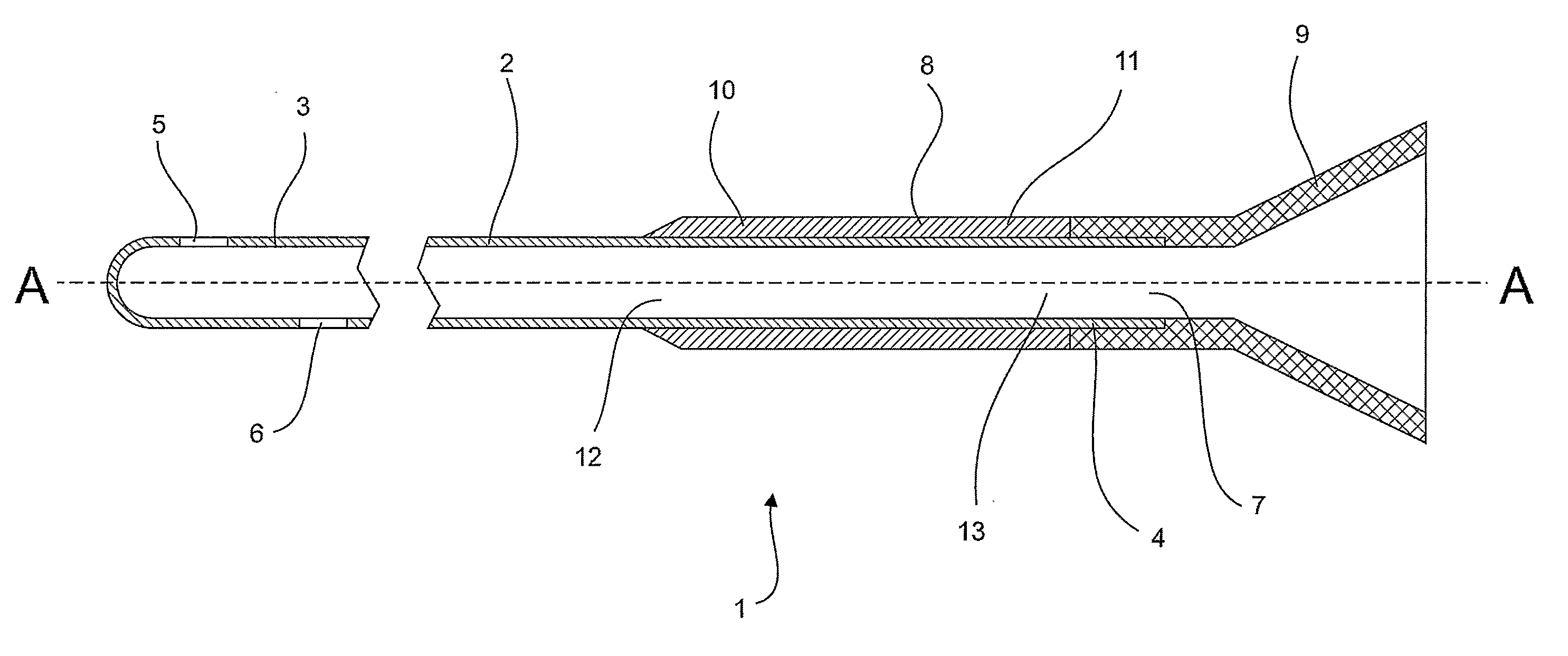
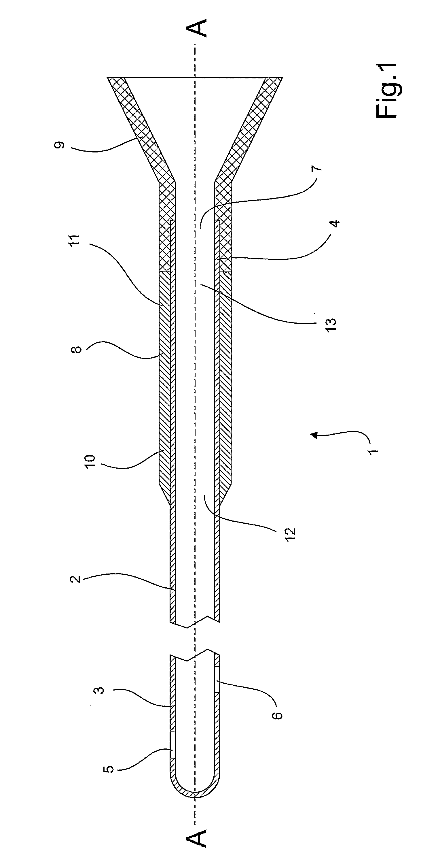
[0026]One embodiment of a catheter 1 for voiding a cavity in the human body (not shown) as disclosed herein is shown in FIG. 1 The catheter is shown in section along its longitudinal axis A-A.

[0027]The catheter 1 comprises a first tubular catheter part 2, a second tubular catheter part 8, and a connector 9.

[0028]The first tubular catheter part 2 extends longitudinally along axis A-A between a proximal end 3 and a distal end 4. At the proximal end there is provided two so-called eyelets 5,6 which functions as inlets; and in the distal end there is provided one outlet 7. At the distal end and in communication with the outlet the connector 9 is attached. This allows the first catheter part to be attached to a hose which may guide urine to a urine bag or other type of receptacle.

[0029]For example, as a first tubular catheter part the Speedicath intermittent catheter sold by Coloplast A / S can be used.

[0030]The second tubular catheter part 8 extends longitudinally along axis A-A between a...


PUM

PropertyMeasurementUnit
stiffnessaaaaaaaaaa
outer radiusaaaaaaaaaa
inner radiusaaaaaaaaaa

Abstract

In the following there is disclosed a catheter for voiding a cavity in the human body. The catheter comprises a first tubular catheter part extending longitudinally between a proximal end provided with at least one inlet, and a distal end provided with at least one outlet and a second tubular catheter part extending longitudinally between a proximal end provided with one opening and a distal end provided with a second opening. The catheter further comprises that the first tubular catheter part is longer than the second tubular catheter part; that the second tubular catheter part is arranged on the first tubular catheter at the distal end; and that the first tubular catheter part and the second tubular catheter part are permanently displaceable fixed relative to each other. This provides a catheter which has distal end which is more stable than conventional intermittent catheters and thus is easier to insert with a reduced risk that the catheter bends or kinks during catherisation.

Description

TECHNICAL FIELD [0001]The present invention relates to a catheter and a method of producing such, which is easy to insert and manufacture.BACKGROUND [0002]Intermittent catherisation is often used in order to void the bladder for people who are not capable of voluntarily do so. Today many types of catheters are available, many suitable for different urinary channel sizes and urethra lengths. In particular the urethra of men is longer than that of women and thus longer catheters are needed for men in order to successfully void the bladder.[0003]At the same time a certain amount of flexibility of the catheter is necessary for it to follow the curvature of the urethra, for example when passing the prostate.[0004]However, long and flexible catheters are difficult to handle as the catheter tend to bend or kink unintentionally during insertion, which complicates the catherisation process. In particular as a large number of intermittent catheter user already might have a handicap which impa...

Claims


Application Information

Patent Timeline
Patent Type & Authority Applications(United States)
IPC IPC(8): A61M25/00B29C65/54
CPCA61M25/0009A61M2025/0098A61M25/007
Inventor SCHERTIGER, LARS OLAV
Owner COLOPLAST AS
Why Eureka
Try Eureka