Canisters

a canister and canister body technology, applied in the field of canisters, can solve the problems of inevitable increase of manufacturing costs and complicated construction of the canister b>101/b>

Active Publication Date: 2011-09-08
AISAN IND CO LTD
View PDF8 Cites 31 Cited by
  • Summary
  • Abstract
  • Description
  • Claims
  • Application Information

AI Technical Summary

Benefits of technology

[0011]A canister includes a first fuel vapor adsorption device and a second fuel vapor adsorption device. The second fuel vapor adsorption device can adsorb a part of fuel vapor that still remains in a gas after desorption by the first fuel vapor adsorption device. The second fuel vapor adsorption device inclu

Problems solved by technology

Therefore, the construction of the canister 101 is complic

Method used


Image

  • Canisters
  • Canisters
  • Canisters

Examples


first example

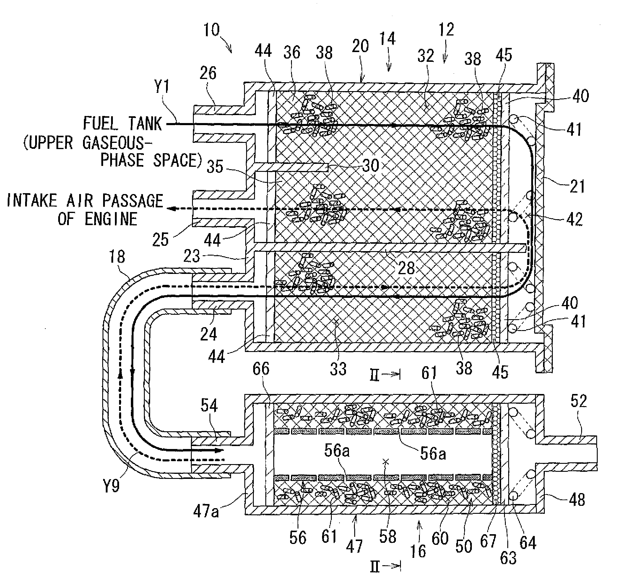
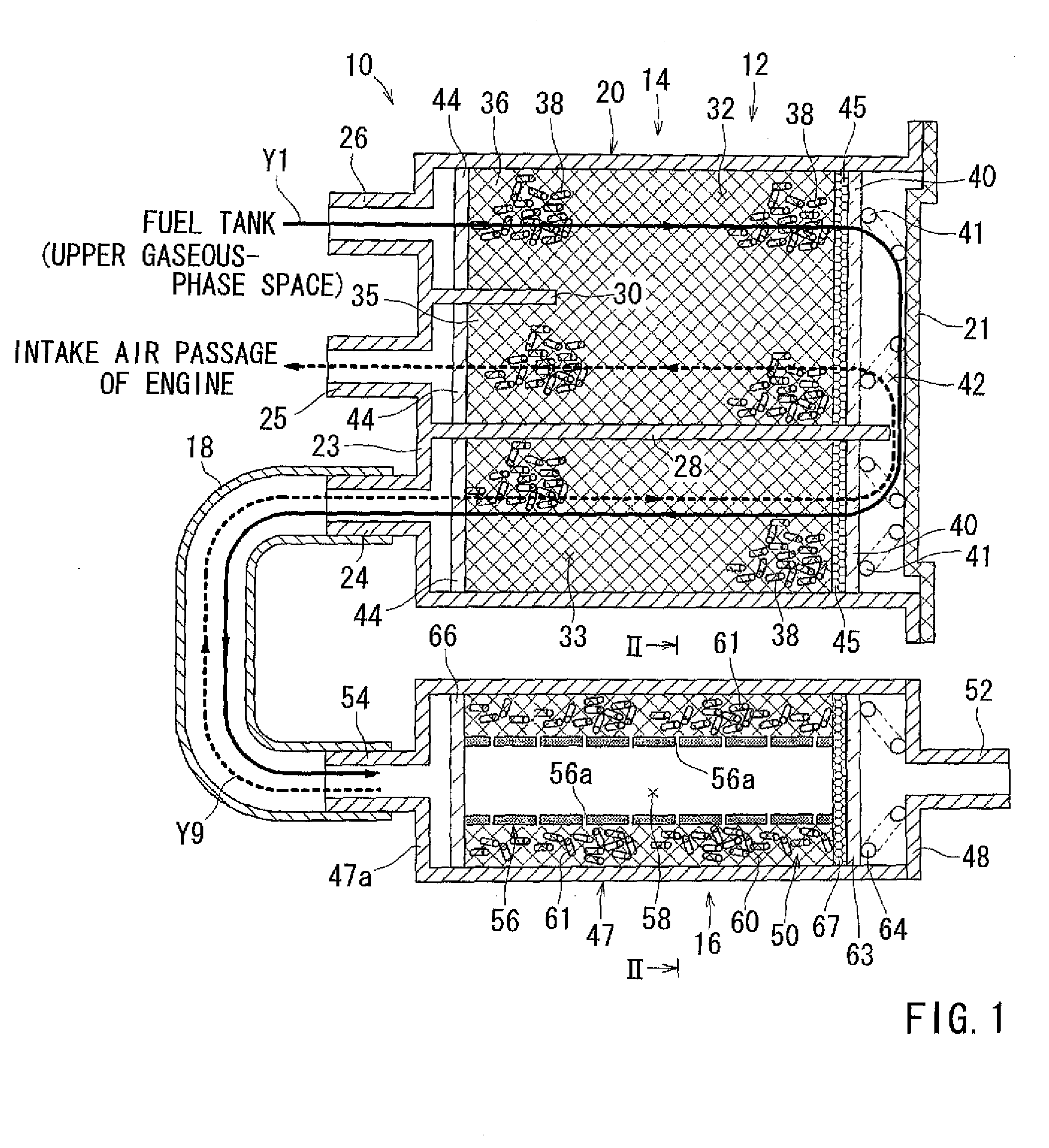
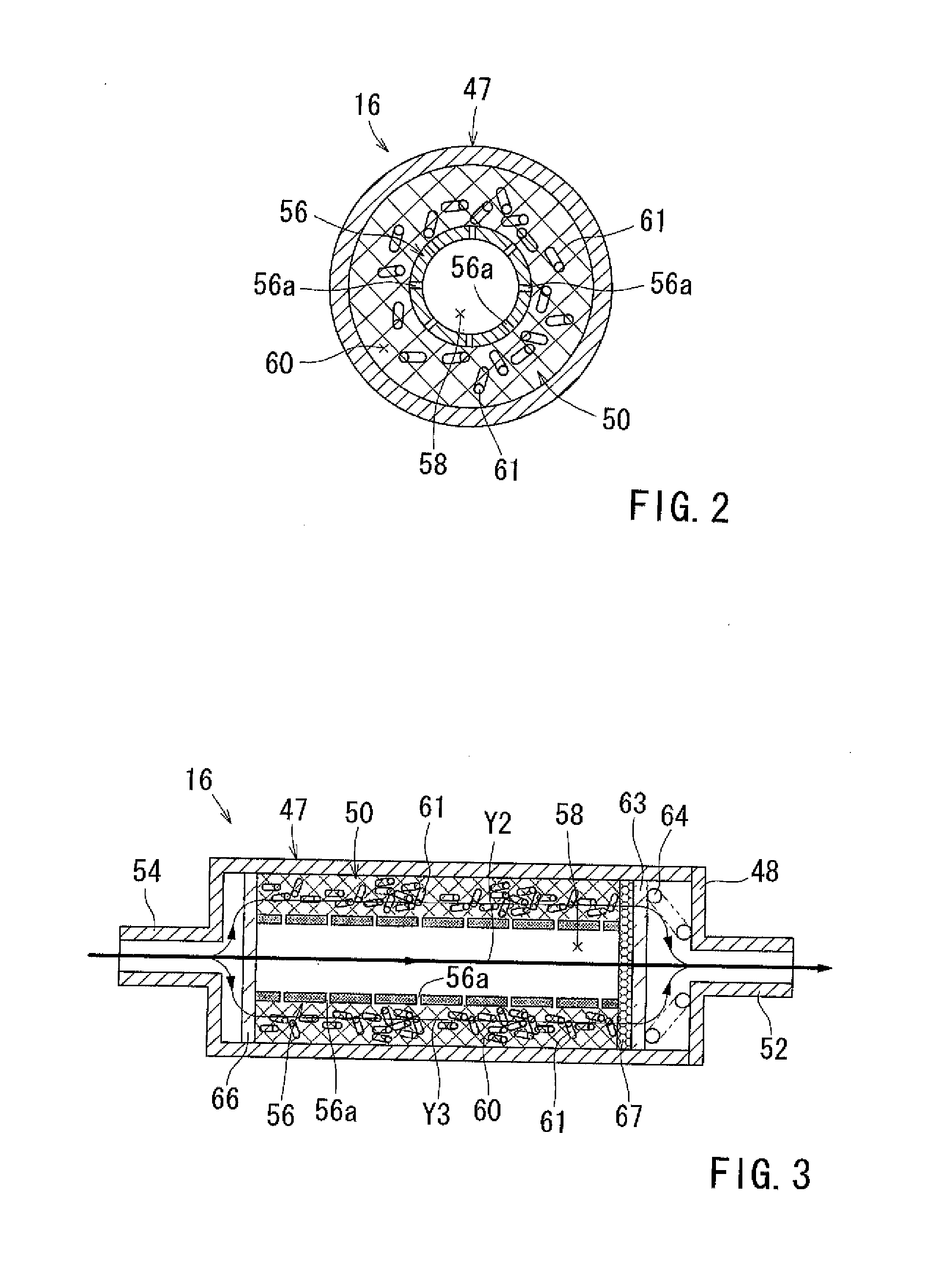
[0034]A canister according to a first example will now be described with reference to FIGS. 1 to 5. Referring to FIGS. 1 to 2, there is shown a canister 10 in a horizontal sectional view and a sectional view taken along line II-II in FIG. 1, respectively. The canister 10 is designed for mounting to a vehicle, such as an automobile (not shown), and in this connection, the left side, the right side, the lower side and the upper side as viewed in FIG. 1 will be referred to as a front side, a rear side, a left side and a right side of the canister 10, respectively, for the purpose of explanation.

[0035]Referring to FIG. 1, the canister 10 has a case 12. The case 12 includes a first case 14, a second case 16 and a communication pipe 18. The second case 16 is a separate member from the first case 14. The communication pipe 18 communicates between a second adsorption chamber 33 defined in the first case 14 and an atmospheric communication chamber 50 defined in the second case 16. The first ...

second example

Alternative Examples of Second Example

[0054]As an alternative example of the second example, it may be configured such that the space on the outer side of the partitioning members 70 serves as the air flow passage 58, while the space within each of the partitioning members 70 serves as the adsorption material passage 60. According to this arrangement, it is possible to provide a plurality of the adsorption material passages 60. In another alternative example, three or more parallel partitioning members 70 may be provided for defining therein the air flow passages 58 or the adsorption material passages 60.

third example

[0055]A third example will now be described with reference to FIG. 8. Referring to FIG. 8, two inner and outer cylindrical tubular partitioning members 72 and 73 are disposed coaxially within the atmospheric communication chamber 50. In this example, the space between the partitioning members 72 and 73 serves as the air flow passage 58, while the space within the inner partitioning member 72 and the space on the outer side of the partitioning member 73 serves as the adsorption material chambers 60. A plurality of gas passage holes 72a and 73a are dispersively formed in the portioning members 72 and 73 to extend therethrough in the diametrical direction, respectively. The gas passage holes 72a communicate between the air flow passage 58 defined on the outer side of the inner partitioning member 72 and the air flow passage 60 defined within the inner partitioning member 72. The gas passage holes 73a communicate between the air flow passage 58 defined within the outer partitioning memb...


PUM


Abstract

A canister includes a first fuel vapor adsorption device and a second fuel vapor adsorption device. The second fuel vapor adsorption device can adsorb a part of fuel vapor that still remains in a gas after desorption by the first fuel vapor adsorption device. The second fuel vapor adsorption device includes a first passage containing a fuel vapor adsorption material and a second passage containing no fuel vapor adsorption material. The first passage and the second passage allow the gas to flow therethrough. A gas introduction device allows the fuel vapor to flow from the second passage into the first passage.

Description

[0001]This application claims priority to Japanese patent application serial numbers 2010-045310 and 2011-010619, the contents of which are incorporated herein by reference.BACKGROUND OF THE INVENTION[0002]1. Field of the Invention[0003]The present invention relates to canisters that can be used in fuel vapor processing apparatus which process fuel vapor produced in internal combustion engines of automobiles.[0004]2. Description of the Related Art[0005]A known canister is disclosed, for example, in Japanese Laid-Open Patent Publication No. 2002-266709. Referring to FIG. 14, there is shown a canister 101 disclosed in this publication.[0006]As shown in FIG. 14, the canister 101 includes a case 102, a main adsorption material 113 and an auxiliary adsorption material 114 disposed within the case 102. A main chamber (including a first chamber 121 and a second chamber 122) and an auxiliary chamber 123 communicating with the main chamber (i.e., the first chamber 121 and the second chamber ...

Claims


Application Information

Patent Timeline
IPC IPC(8): B01D53/02
CPCB01D53/02F02M25/0854B01D2253/102B01D2259/4516F02M2025/0881B01D53/0415F02M25/089B60K2015/03514B01D2257/702
Inventor HASEGAWA, MASAKAZUSUGIURA, MASAHIRO
Owner AISAN IND CO LTD
Why Eureka
Try Eureka