Faucet diverter device

a diverter and faucet technology, applied in water installations, thin material processing, construction, etc., can solve the problems of water outflow, reduced life time, and increased cost and volume, and achieve the effect of simple and intuitive operation methods, and reducing the number of switch handles

Inactive Publication Date: 2011-09-08
DELUXE BRASSWARE
View PDF5 Cites 2 Cited by
  • Summary
  • Abstract
  • Description
  • Claims
  • Application Information

AI Technical Summary

Benefits of technology

[0006]The main object of the present invention is to reduce the number of switch handles for controlling water supply and the whole volume can also be reduced so as to provide a simpler and more intuitive operation method, thereby reducing the manufacturing cost and assembling cost and also effectively enhancing the yield.
[0007]Another object of the present invention is to solve the problem of damage to the faucet main body caused by the rubber washer with short life time and the incapability of the whole faucet device due to the stuck rubber washer in the faucet main body.
[0008]For achieving the objects described above, the present invention provides a faucet diverter device includes a faucet main body and a diverter valve. The faucet main body includes a first channel and a second channel for respectively passing therethrough a first fluid and a second fluid. The diverter valve, is connected with the faucet main body, comprising a turning valve thereinside, a first inlet communicated with the first channel and the turning valve, a second inlet communicated with the second channel and the turning valve, a first diverting outlet, a second diverting outlet, and a pivot connected with the turning valve for turning the turning valve. The first fluid and the second fluid respectively flow into the turning valve through the first inlet and the second inlet, and the turning valve includes a mixing space for blending the first fluid with the second fluid to generate a mixed fluid, and a hole corresponding to the first diverting outlet and the second diverting outlet, wherein through turning the pivot to move the turning valve, the hole can be moved to a first position corresponding to the first diverting outlet, a second position corresponding to the second diverting outlet or a cut-off position, so that the mixed fluid can be selected to output through the first diverting outlet or the second diverting outlet by moving the hole, and the cut-off position is a position other than the first position and the second position, for preventing the mixed fluid from flowing out.
[0009]Consequently, the faucet diverter device of the present invention utilizes turning the pivot to move the hole, so that the mixed fluid can be selected to output from the first diverting outlet or the second diverting outlet, or stop to output as the hole is moved to the cut-off position. Moreover, the present invention only employs one diverter valve to select the diverting outlets for outputting the mixed fluid or to cut-off the outflow of the mixed fluid, so that the whole volume of the faucet diverter device can be reduced and the operation also becomes easier, as compared with the prior art, thereby effectively enhancing the yield of manufacture and reducing the assembling cost. In addition, the turning valve is made of ceramics which has high wear resistance and excellent acid and alkali resistance, so that it can provide a longer life time and a lower failure probability, thereby not only the maintenance or replacement probability but also the maintenance cost can be reduced.

Problems solved by technology

M247741 is complicated and has to yield to the multiple independent water supplying switches, so that both the cost and the volume become higher, and further, since each independent water supplying switch can be turned on at the same time, the user might erroneously touch the independent water supplying switch so as to cause an unpredictable water outflow.
However, since the washer must be made by a flexible material, such as, a rubber, if the rubber is worn down, it might cause a water leakage, and further, because the rubber is easily deteriorated by the alternate high and low temperatures, the life time thereof might be reduced.
Besides, the acid and alkali resistance of the rubber is also poor, so that after a period of time, it might become difficult to turn the eccentric shaft, and finally become stuck and can not be used any more.

Method used


Image

  • Faucet diverter device
  • Faucet diverter device
  • Faucet diverter device

Examples


Embodiment Construction

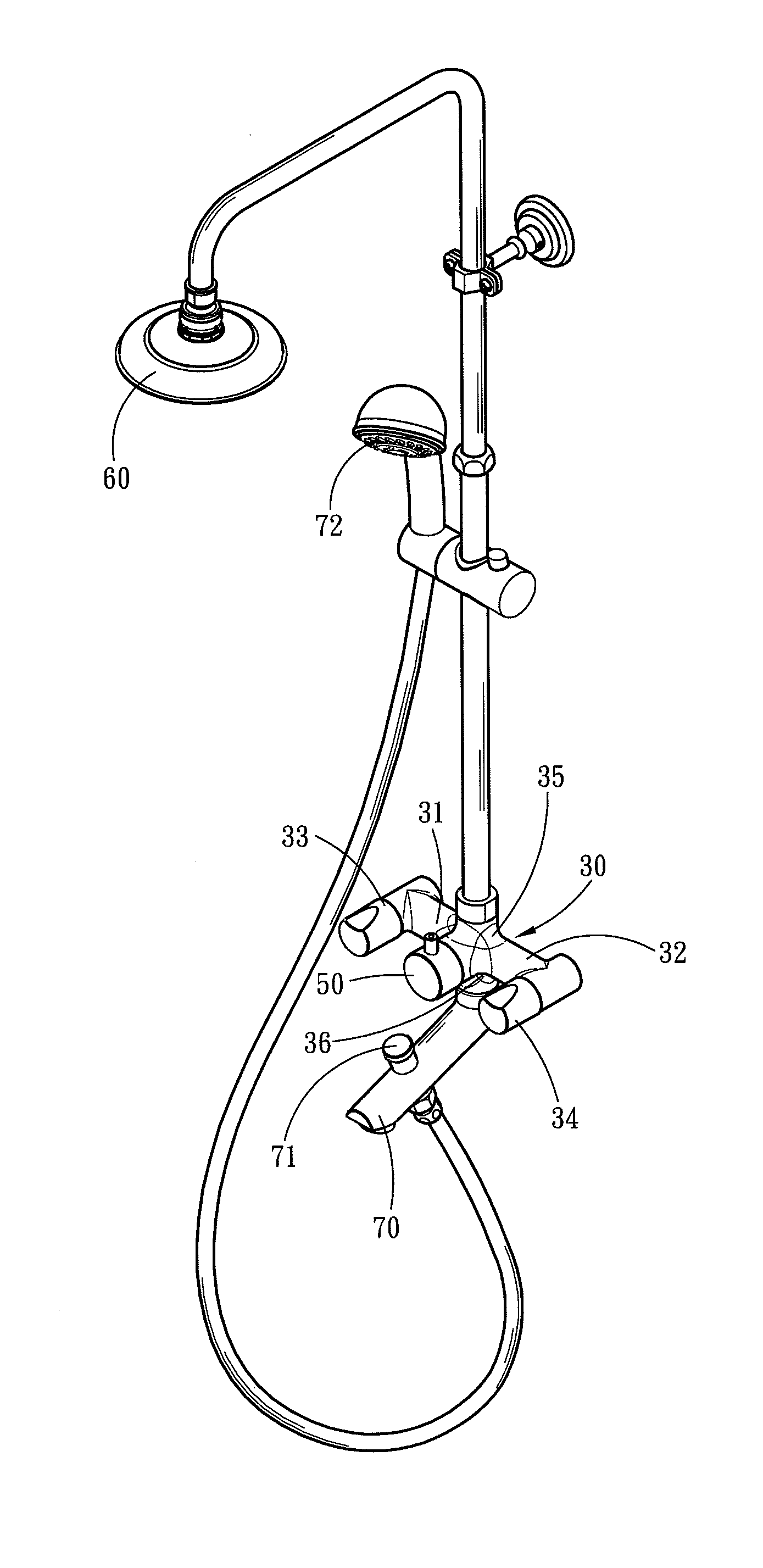
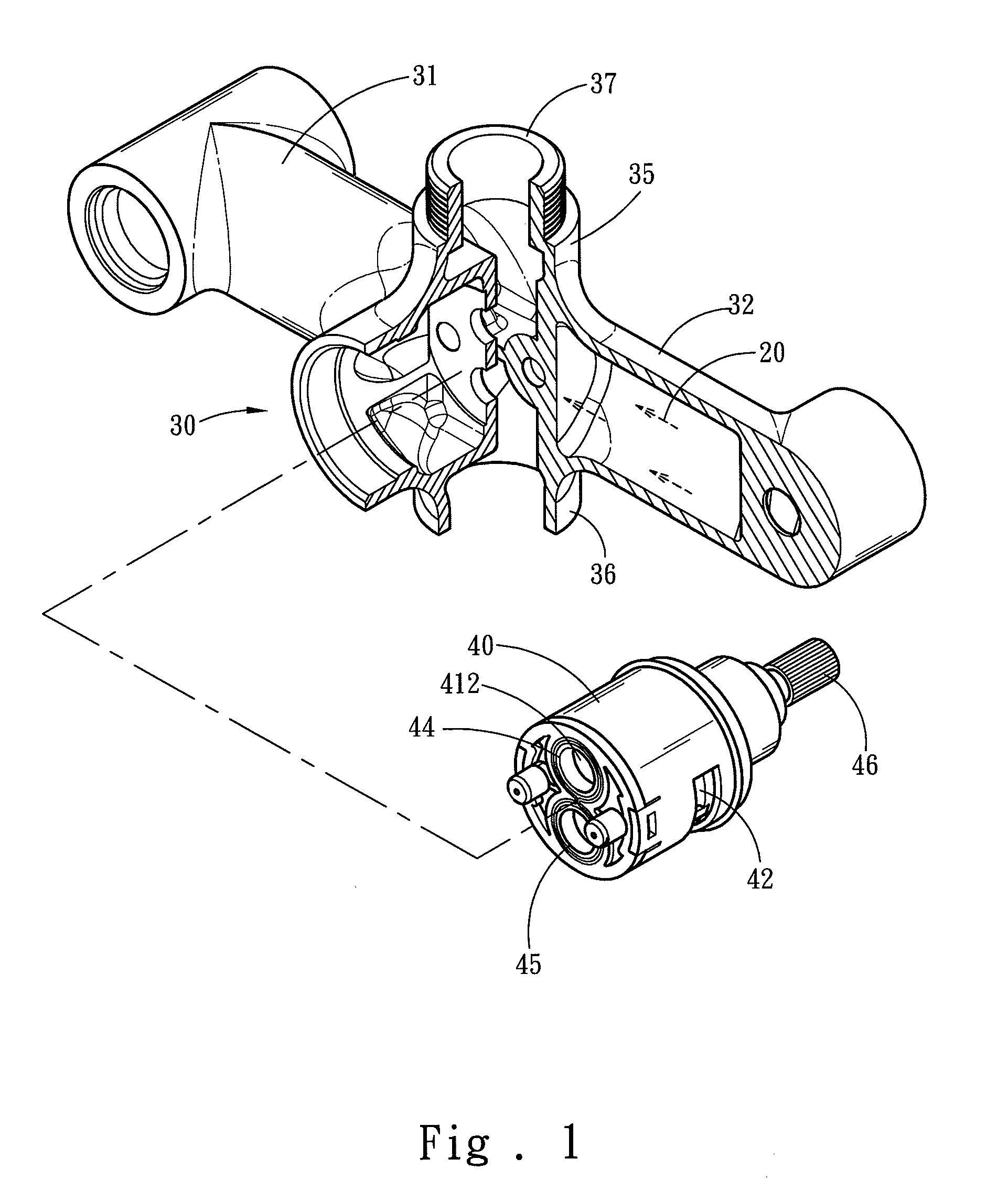
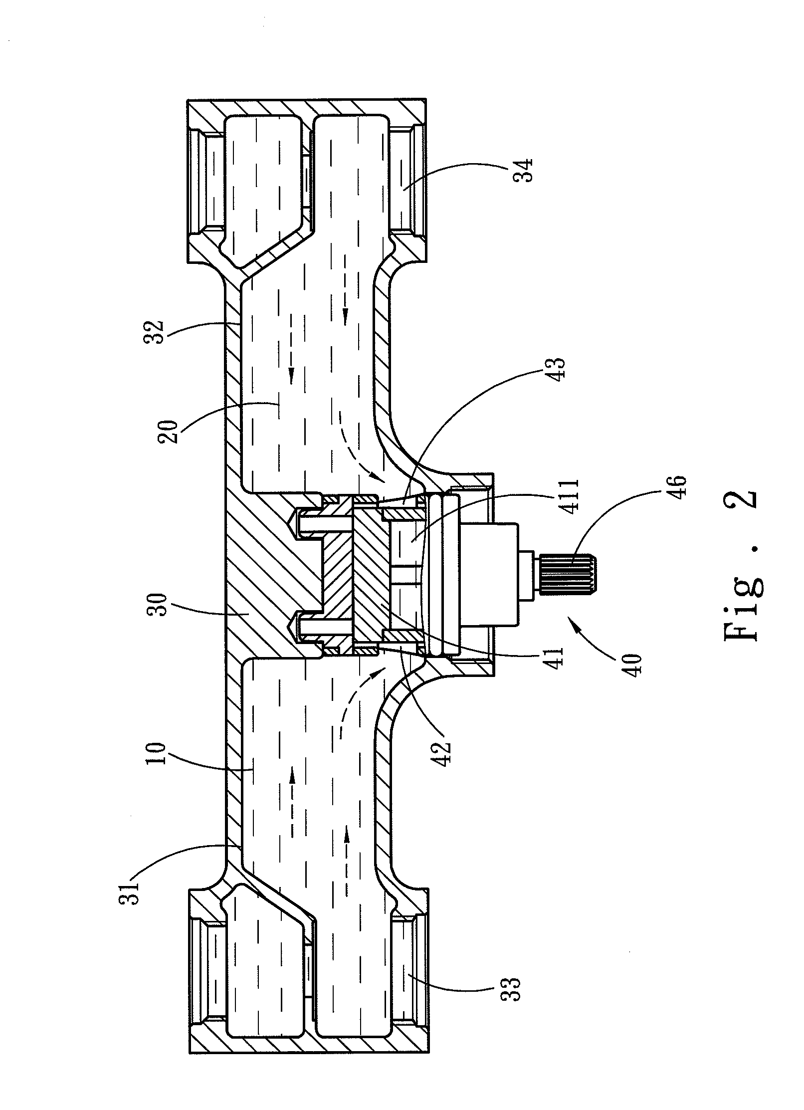
[0017]Please refer to FIG. 1, FIG. 2 and FIG. 3. As shown, the present invention is related to a faucet diverter device, including a faucet main body 30 and a diverter valve 40. The faucet main body 30 has a first channel 31 and a second channel 32 for respectively passing therethrough a first fluid 10 and a second fluid 20. The diverter valve 40, which is connected with the faucet main body 30, has a turning valve 41 thereinside, a first inlet 42 communicated with the first channel 31 and the turning valve 41, a second inlet 43 communicated with the second channel 32 and the turning valve 41, a first diverting outlet 44, a second diverting outlet 45 and a pivot 46 connected with the turning valve 41 for turning the turning valve 41. The first fluid 10 and the second fluid 20 respectively flow into the faucet main body 30 through the first channel 31 and the second channel 32, and respectively pass through the first inlet 42 and the second inlet 43 to enter the turning valve 41 insi...


PUM


Abstract

A faucet diverter device includes a faucet main body and a diverter valve. The faucet main body includes a first channel and a second channel for respectively passing therethrough a first fluid and a second fluid. The diverter valve, which is connected with the first channel and the second channel, includes a turning valve thereinside, a first diverting outlet, a second diverting outlet, and a pivot connected with the turning valve for turning the turning valve. The first fluid and the second fluid respectively flow into the turning valve of the diverter valve for blending with each other to generate a mixed fluid. The turning valve further includes a hole, and through turning the pivot to move the turning valve, the hole can be moved to a first position corresponding to the first diverting outlet, a second position corresponding to the second diverting outlet or a cut-off position.

Description

FIELD OF THE INVENTION[0001]The present invention is related to a diverter device, and more particularly to a faucet diverter device whose outflow can be altered through turning a switch.BACKGROUND OF THE INVENTION[0002]R.O.C patent No. M247741, entitled “Thermostatic Faucet Structure”, disclosed that by cooperating a preliminary setting of control switches for cold and hot waters for adjusting the flow amount with independent water supplying switches for water outlets, such as, a shower nozzle, a shower pipe, and a lower drain pipe, the user can adjust the water temperature via the control switches for hot and cold waters, and further control the water amount directly via the independent water supplying switches. Accordingly, the user can have steady flows of hot and cold waters through fixing the control switches, so that during showering, there is not more need to frequently adjust the control switches for achieving the desired water temperature, which wastes not only time but al...

Claims


Application Information

Patent Timeline
Patent Type & Authority Applications(United States)
IPC IPC(8): E03C1/02
CPCE03C1/02Y10T137/86493E03C2201/30E03C1/0408E03C1/04E03C1/0404
Inventor HSIEH, YU-YUHONG, MIN-NAN
Owner DELUXE BRASSWARE
Why Eureka
Try Eureka