Brake device lubrication device and method for controlling same

a technology of lubrication device and brake device, which is applied in the direction of braking system, braking components, instruments, etc., can solve the problems of reducing the temperature of the rotating member, and reducing the supply amount of lubricant, so as to suppress the overheating effect, and suppress the loss of driving force in the brake devi

Active Publication Date: 2011-09-08
KOMATSU LTD
View PDF5 Cites 4 Cited by
  • Summary
  • Abstract
  • Description
  • Claims
  • Application Information

AI Technical Summary

Benefits of technology

[0017]In this control method, when the brake device switches from the braking state to the released state, the amount of lubricant is reduced to the second supply amount when the delay time has elapsed, rather than being immediately reduced to the second supply amount. The delay time is acquired from the relationship of correspondence between the delay time and the braking time stored in the storage unit, and from the braking time tha

Problems solved by technology

Even if the brake device is in a released state in which the rotating member and the fixed member are not pressed together, in a case in which a large amount of lubricant is present between the rotating member and the fixed member, A loss of driving force may occur due to a portion of the driving force of the output shaft being transmitted from the rotating member to the lubricant.
However, in the brake device, the temperature of the rotating member sometimes does not adequately decrease

Method used


Image

  • Brake device lubrication device and method for controlling same
  • Brake device lubrication device and method for controlling same
  • Brake device lubrication device and method for controlling same

Examples


Embodiment Construction

Configuration

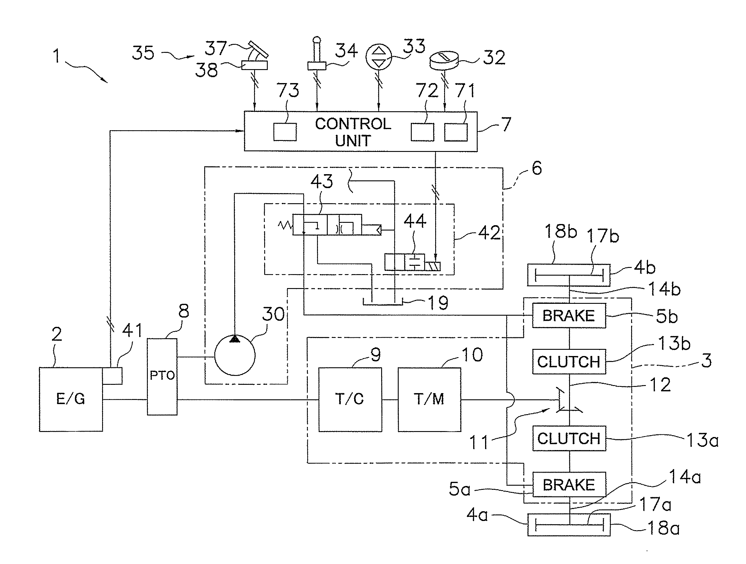
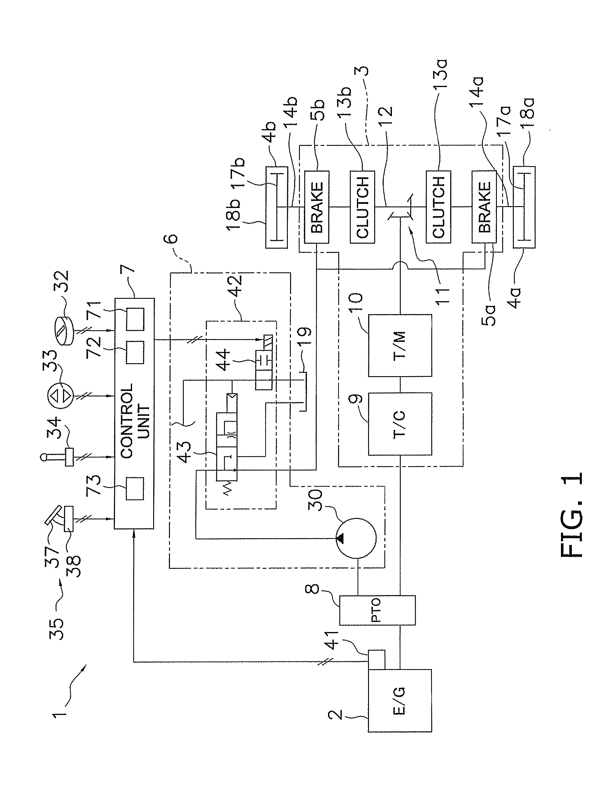
[0027]FIG. 1 is a view showing the overall system configuration of a work vehicle 1 which is provided with the lubrication device according to an embodiment of the present invention. The work vehicle 1 is a bulldozer, for example, and is provided with an engine 2, a drive train mechanism 3, a pair of travel devices 4a, 4b, a lubricant supply unit 6, various operation units 32 through 35, a control unit 7, and other components. Among these constituent components, the lubricant supply unit 6 and the control unit 7 constitute a lubrication device for supplying a lubricant for cooling to brake devices 5a, 5b. The various operation units 32 through 35 will be described in detail hereinafter.

[0028]The engine 2 is a diesel engine, and the output of the engine 2 is controlled by adjusting the injected amount of fuel from a fuel injection pump not shown in the drawing. Specifically, the engine speed and the fuel injection amount are adjusted according to load so that the actual ...


PUM


Abstract

A brake device lubrication device includes a lubricant supply unit and a control unit. The control unit includes a braking timer, a release timer and a storage unit. The control unit is configured to control the lubricant supply unit so as to supply a predetermined first supply amount of lubricant to a brake device when the brake device is in a braking state, to acquire a delay time corresponding to a braking time counted by the braking timer from a relationship of correspondence between the braking time and the delay time stored by the storage unit when the brake device is switched from the braking state to a released state, and to switch a supply amount of lubricant from the first supply amount to a second supply amount which is smaller than the first supply amount when the release time counted by the release timer reaches the acquired delay time.

Description

CROSS-REFERENCE TO RELATED APPLICATIONS[0001]This national phase application claims priority to Japanese Patent Application No. 2008-319452 filed on Dec. 16, 2008. The entire disclosure of Japanese Patent Application No. 2008-319452 is hereby incorporated herein by reference.TECHNICAL FIELD[0002]The present invention relates to a brake device lubrication device and to a method for controlling the same.BACKGROUND ART[0003]In a brake device, braking force is generated by the pressing together of a rotating member which rotates together with an output shaft, and a fixed member which is fixed to the vehicle body side, and friction generates heat in the rotating member. A lubrication device therefore cools the rotating member by feeding lubricant between the rotating member and the fixed member, and keeps the temperature of the rotating member from increasing.[0004]Even if the brake device is in a released state in which the rotating member and the fixed member are not pressed together, ...

Claims


Application Information

Patent Timeline
IPC IPC(8): F16D65/78F16D65/00G06F19/00B60T17/00
CPCB60T5/00F16D2065/787F16D65/853
Inventor FUJINO, TANEAKISASADA, ATSUSHISHIMADA, KENJIRO
Owner KOMATSU LTD
Why Eureka
Try Eureka