
Liquid heating devices

a heating device and liquid technology, applied in the direction of electric heating for furnaces, furnaces, kitchen equipment, etc., can solve the problems of increasing the time taken for water to heat from cold, inconvenience for users, and increasing the time taken for it to boil, so as to reduce the amount of steam, reduce the “thermal shock”, and minimize the reset time of a bimetallic actuator

Inactive Publication Date: 2011-09-08
STRIX LTD
View PDF18 Cites 16 Cited by
  • Summary
  • Abstract
  • Description
  • Claims
  • Application Information

AI Technical Summary

Benefits of technology

[0010]Thus it will be seen by those skilled in the art that in accordance with the invention a device which can supply hot liquids such as water comprises two distinct chambers, for heating and dispensing respectively. The heating chamber is preferably configured to heat a body of liquid, e.g. water, therein to boiling, with the increase in pressure associated with boiling forcing the heated liquid into the conduit and venting it into the dispensing chamber. This means that the dangerous pressurized boiling water and steam are safely ejected into the dispensing chamber whilst the water can be dispensed at the outlet in a slower, more uniform flow which is essentially independent of the water still coming in from the heating chamber. In other words, the dispensing chamber acts effectively to decouple the outlet from the heating chamber from the outlet to the user.
[0061]In any of the embodiments set out above the mechanism for switching off the element could be configured such that there is enough pressure for all or substantially all of the liquid being heated in the heating chamber to be ejected. However in accordance with some embodiments envisaged the configuration of the heating chamber and element switching-off mechanism could be such as deliberately to leave some liquid remaining in the heating chamber. This could be beneficial in reducing the “thermal shock” suffered by the element and / or heating chamber when fresh, colder liquid is added, e.g. from a reservoir. It is also beneficial in reducing the amount of steam generated after the bulk of the liquid has been ejected (and so minimizing the reset time of a bimetallic actuator if provided). It also reduces the risk of sufficient steam being produced at the beginning of the heating part of the cycle to terminate the cycle prematurely. For example, the Applicant has found that by making the conduit tube referred to above shorter, some liquid is left in the heating chamber at the end of the cycle. As previously discussed, this amount could be variable—e.g. by raising or lowering the end of the conduit tube within the heating chamber. In a set of preferred embodiments however the heater is adapted to retain liquid preferentially in one or more parts thereof, e.g. in a heated region. For example where the heater comprises a sheathed heating element attached to the underside of a heating plate, the plate can be formed with a depression above some or all of the element. This minimizes the volume left behind (and so the energy wasted in each heating cycle) but ensures that the water is where it is most needed.

Problems solved by technology

In the case of the kettle, the time taken for the water to heat from cold (i.e. the temperature from which it is drawn from the tap) is seen as inconvenient to users, even those using very high power kettles (of the order of 3 kilowatts).
This is particularly so given the difficulty in estimating the volume of water required when the kettle is being filled and the attendant tendency to boil more water than is needed which of course increases the time taken for it to boil.
On the other hand, if water is kept for a prolonged period of time either at or just below boiling, a significant amount of energy will be required to counter the unavoidable heat loss.
However, these devices are typically based on a tubular flow heater and the applicant has appreciated some significant drawbacks to this arrangement.
Another drawback is that although the heater heats up relatively quickly, there is inevitably an initial volume of water which passes through the heater which is not heated to the target temperature.
The combination of these two factors means that in practice the water provided by such devices is at well below boiling point by the time it is dispensed, making it unsuitable for example for making tea and thereby limiting its consumer appeal.

Method used


Image

  • Liquid heating devices
  • Liquid heating devices
  • Liquid heating devices

Examples


Embodiment Construction

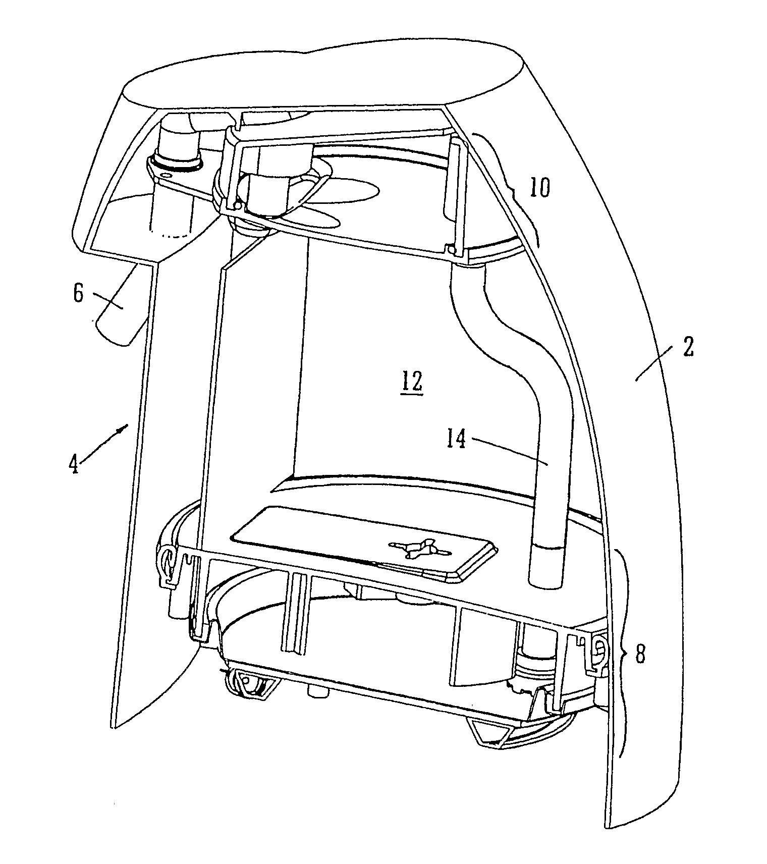
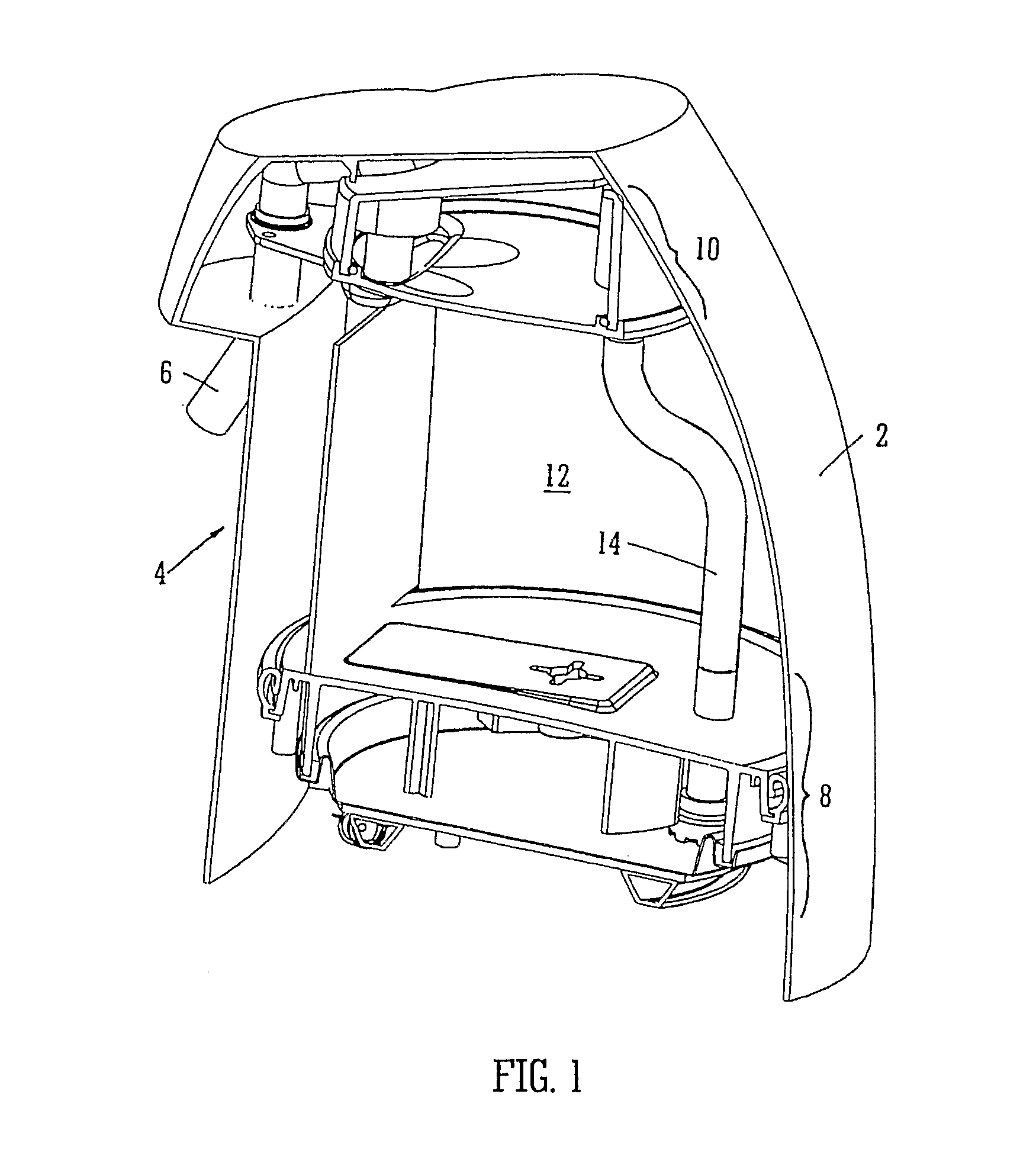
[0085]Turning firstly to FIG. 1 there is shown a hot water dispensing vessel which has an outer body 2 with a front “undercut” portion 4 defining a space that permits a user to place a cup or other receptacle under an outlet spout 6. Inside, the vessel is divided into three main parts. In the lower part of the vessel is a heating chamber 10 which will be described in greater detail below with reference to FIGS. 2 and 3. At the upper part of the vessel is a dispensing chamber 10 which will be described in greater detail below with reference to FIG. 4. Between the heating chamber 8 and the dispensing chamber 10 is a water reservoir section 12. This can be filled using a suitable opening in the body (not shown). A conduit tube 14 passes through the water reservoir 12 and connects the heating chamber 8 to the dispensing chamber 10.

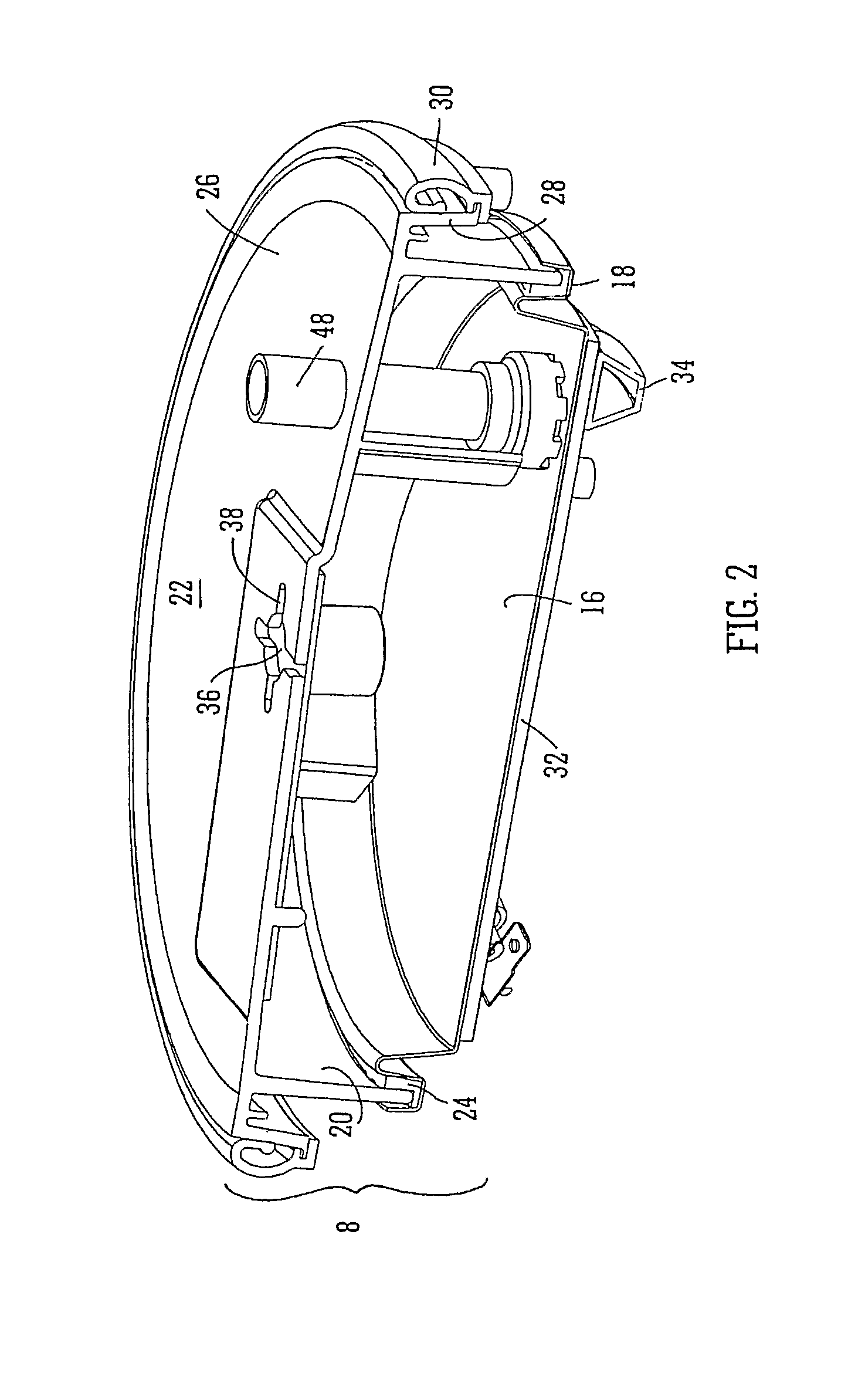
[0086]Turning now to FIGS. 2 and 3, the heating chamber 8 may be seen in more detail. The base of the heating chamber is defined by an underfloor heating elem...


PUM


Abstract

An apparatus for heating liquid comprises a heating chamber, a dispensing chamber and a conduit. The conduit conveys heated liquid from the heating chamber to the dispensing chamber for automatic dispensing. The dispensing chamber has valve means through which the heated liquid is dispensed, which are operable to interrupt the automatic dispensing. An apparatus for heating liquid comprises a heating chamber, a dispensing chamber and a conduit. The conduit conveys heated liquid from the heating chamber to the dispensing chamber for automatic dispensing. The apparatus comprises means for determining a volume of heated liquid to be dispensed automatically.

Description

[0001]This application is entitled to the benefit of, and incorporates by reference essential subject matter disclosed in PCT Application No. PCT / GB2009 / 002378 filed on Oct. 7, 2009, which claims priority to Great Britain Application No. 0818303.0 filed Oct. 7, 2008, PCT Application No. PCT / GB2008 / 004252 filed Dec. 23, 2008, Great Britain Application No. 0900424.3 filed Jan. 12, 2009 and Great Britain Application No. 0910321.9 filed Jun. 15, 2009. This application is also related to U.S. patent application Ser. Nos. 12 / 810,438 filed Oct. 28, 2010 and 12 / 810,450 filed Oct. 28, 2010.BACKGROUND OF THE INVENTION[0002]1. Technical Field[0003]This invention relates to devices for heating water or other liquids, particularly heating a relatively small volume of liquid in a short space of time.[0004]2. Background Information[0005]There is a common need almost all over the world to heat water in order to make beverages. In the UK and other parts of Europe, it is common for most households to...

Claims


Application Information

Patent Timeline
Patent Type & Authority Applications(United States)
IPC IPC(8): A47J31/44A47J31/54A47J31/56A47J31/46
CPCA47J31/465A47J27/21191A47J27/21166
Inventor GARVEY, VINCENT JOSEPHMOUGHTON, COLINNICHOL, NORMAN ERICWHITE, JONATHAN MICHAEL
Owner STRIX LTD
Features
  • Generate Ideas
  • Intellectual Property
  • Life Sciences
  • Materials
  • Tech Scout
  • Unparalleled Data Quality
  • Higher Quality Content
  • 60% Fewer Hallucinations
Learn More