Process and Apparatus for Reducing Thermal Shock in a Hydrocarbon Steam Cracking Furnace

a technology of hydrocarbon steam cracking furnace and thermal shock reduction, which is applied in the field of thermal cracking hydrocarbons, can solve the problems of combusting fuel in the firebox burner, achieve the effects of reducing the amount of flue gas generated, facilitating conducting flue gas, and reducing the amount of thermal shock during a blower shut-off even

Active Publication Date: 2017-03-23
EXXONMOBIL CHEM PAT INC
View PDF5 Cites 4 Cited by
  • Summary
  • Abstract
  • Description
  • Claims
  • Application Information

AI Technical Summary

Benefits of technology

[0008]It has been found that thermal shock during a blower shut-off event can be reduced by providing a tall natural draft flue gas stack, conducting a portion of flue gas around the blower to the stack through a blower bypass conduit, and reducing the amount of flue gas generated. The tall stack develops draft to allow sufficient flue gas generation to maintain the radiant tubes near operating temperature and avoid thermal shock when an undesired blower shut-off event occurs. The blower bypass conduit allows the flue gas to be redirected around the blower when the blower stops operating. A set of dampers can facilitate conducting flue gas through either the blower, blower bypass conduit, or both. A control system and sensor can identify a blower shut-off event and take action.
[0009]In one aspect, embodiments of the invention provide a method of reducing thermal shock in one or more radiant tubes of a furnace. The furnace comprises a firebox with one or more burners and one or more radiant tubes, a convection section in fluid communication with the firebox, a flue gas stack, a blower, and a blower bypass conduit. The blower and blower bypass conduit provide separate fluid communication paths so flue gas may travel between the convection section and the flue gas stack through either or both paths. The method comprises several steps: First, provide fuel to the furnace. Second, combust the fuel in the firebox burners to generate flue gas. Third, use the blower to conduct the flue gas away from the firebox through the convection section, blower, and out the flue gas stack. Fourth, monitor a parameter indicative of an imminent or present blower shut-off event. Fifth, when the parameter indicates a blower shut-off event, direct at least a portion of the flue gas from the convection section through the blower bypass conduit instead of directing that portion through the blower. Finally, reduce the amount of flue gas generated in the firebox.
[0010]In another aspect, embodiments of the invention provide a furnace comprising several components. First, the furnace comprises a plurality of hydrocarbon feed conduits and a plurality of dilution steam conduits. The individual steam conduits are in fluid communication with their corresponding hydrocarbon feed conduits. Second, the furnace comprises a plurality of radiant tubes in fluid communication with the combined steam and hydrocarbon feed conduits. The furnace also comprises a firebox. The firebox comprises a plurality of burners for generating flue gas used to heat the exterior of the radiant tubes. The burners heat the radiant tubes providing a cracked hydrocarbon effluent. Third, the furnace comprises a convection section in fluid communication with the firebox for heating the hydrocarbon feed and steam conduits with flue gas generated by the burners. Fourth, the furnace comprises a flue gas stack, a blower, and a blower bypass conduit. The blower and the blower bypass conduit provide separate fluid communication paths for flue gas to flow from the convection section to the flue gas stack. Fifth, the furnace comprises a first damper adapted to control flow of flue gas through the blower and a second damper adapted to control flow of flue gas through the blower bypass conduit. Sixth, the furnace comprises a partial trip valve configured to reduce flue gas generation (by reducing fuel flow) to one or more of the plurality of burners. Seventh, the furnace comprises at least one sensor configured to detect a parameter indicative of a blower shut-off event and a controller in communication with the sensor. The controller is configured to perform the following steps when the sensor indicates a blower shut-off event: (i) close the first damper to reduce flow of flue gas through the blower, (ii) open the second damper to direct at least a portion of the flue gas through the blower bypass conduit, and (iii) close the partial trip valve to reduce flue gas generation.

Problems solved by technology

Second, combust the fuel in the firebox burners to generate flue gas.

Method used


Image

  • Process and Apparatus for Reducing Thermal Shock in a Hydrocarbon Steam Cracking Furnace
  • Process and Apparatus for Reducing Thermal Shock in a Hydrocarbon Steam Cracking Furnace

Examples


Embodiment Construction

[0013]Various aspects will now be described with reference to specific embodiments selected for purposes of illustration. It will be appreciated that the spirit and scope of the process and system disclosed herein is not limited to the selected embodiments. Moreover, it is to be noted that the FIGURE provided herein are not drawn to any particular proportion or scale, and that many variations can be made to the illustrated embodiments. Reference is now made to the FIGURE, wherein like numerals are used to designate like parts throughout. When an amount, concentration, or other value or parameter is given as a list of upper preferable values and lower preferable values, this is to be understood as specifically disclosing all ranges formed from any pair of an upper preferred value and a lower preferred value, regardless whether ranges are separately disclosed.

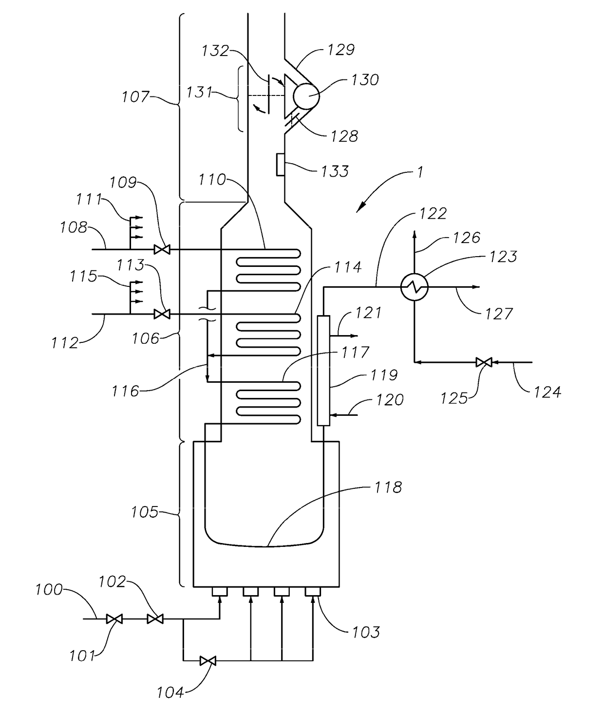
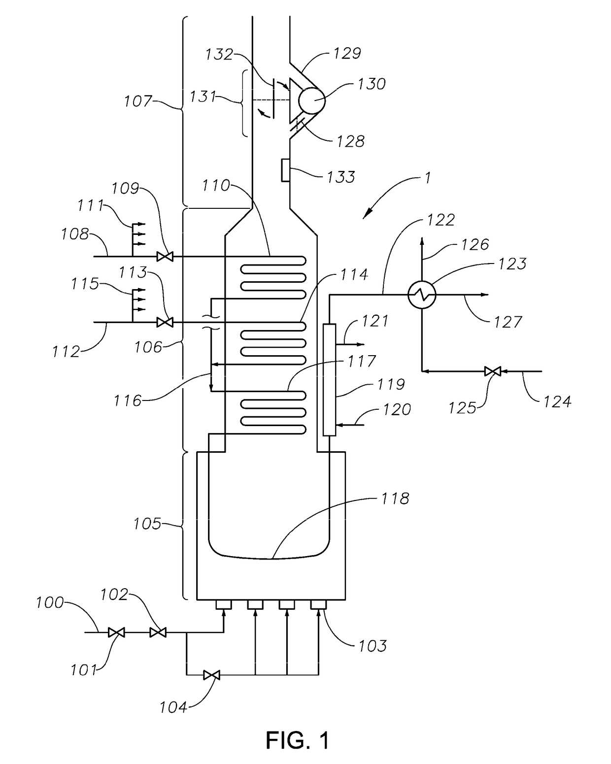
[0014]Referring now to FIG. 1, a non-limiting exemplary embodiment of a steam cracking furnace 1 is illustrated. Fuel comprisin...


PUM

PropertyMeasurementUnit
temperatureaaaaaaaaaa
boiling pointsaaaaaaaaaa
temperatureaaaaaaaaaa

Abstract

A method and apparatus of reducing thermal shock in one or more radiant tubes of a pyrolysis furnace is provided. The apparatus is a furnace comprising a blower and blower bypass conduit providing separate fluid communication paths for flue gas from the convection section to a natural draft flue gas stack. The method comprises the steps of: redirecting at least a portion of the flue gas through the blower bypass conduit when a blower shut-off event is indicated as well as reducing the firing rate of the furnace.

Description

CROSS REFERENCE TO RELATED APPLICATIONS[0001]This application claims the benefits of and priorities to U.S. Ser. No. 62 / 221,307, filed Sep. 21, 2015, and EP 15192280.4, filed Oct. 30, 2015, the disclosures of which are incorporated by reference in their entireties.FIELD OF THE INVENTION[0002]The present invention relates to the field of thermal cracking hydrocarbons for the production of olefins, particularly low molecular weight olefins such as ethylene. More particularly the invention relates to methods and equipment for reducing thermal shock to steam cracking furnace tubes.BACKGROUND OF THE INVENTION[0003]Thermal cracking of hydrocarbon feeds in the presence of steam (“steam cracking”) is a commercially important technology for producing light olefins such as ethylene, propylene, and butadiene. Hydrocarbon feeds can include one or more of ethane, propane, butane, naphtha, heavy gas oils, and crude oil. Steam cracking furnaces for carrying out steam cracking generally include a c...

Claims


Application Information

Patent Timeline
Patent Type & Authority Applications(United States)
IPC IPC(8): C10G9/20C07C4/04C10G9/36F27B1/28
CPCC10G9/206F27B1/28C10G2400/20C10G9/36C10G2300/1081C07C4/04C10G9/16C10G2300/1044F23J2213/70F23N5/245
Inventor SPICER, DAVID B.LE ROY, PHILIPPE J.STEPHENS, GEORGE
Owner EXXONMOBIL CHEM PAT INC
Why Eureka
Try Eureka