
Cooling subsystem for an electrochemical fuel cell system

a fuel cell and subsystem technology, applied in the field of electrochemical fuel cells, can solve the problems of detrimental effects of local heating within the stack on the stack, and achieve the effects of reducing the volume of coolant, quick bringing the temperature of the stack, and improving start-up tim

Inactive Publication Date: 2005-08-11
FORD MOTOR CO +1
View PDF15 Cites 26 Cited by
  • Summary
  • Abstract
  • Description
  • Claims
  • Application Information

AI Technical Summary

Benefits of technology

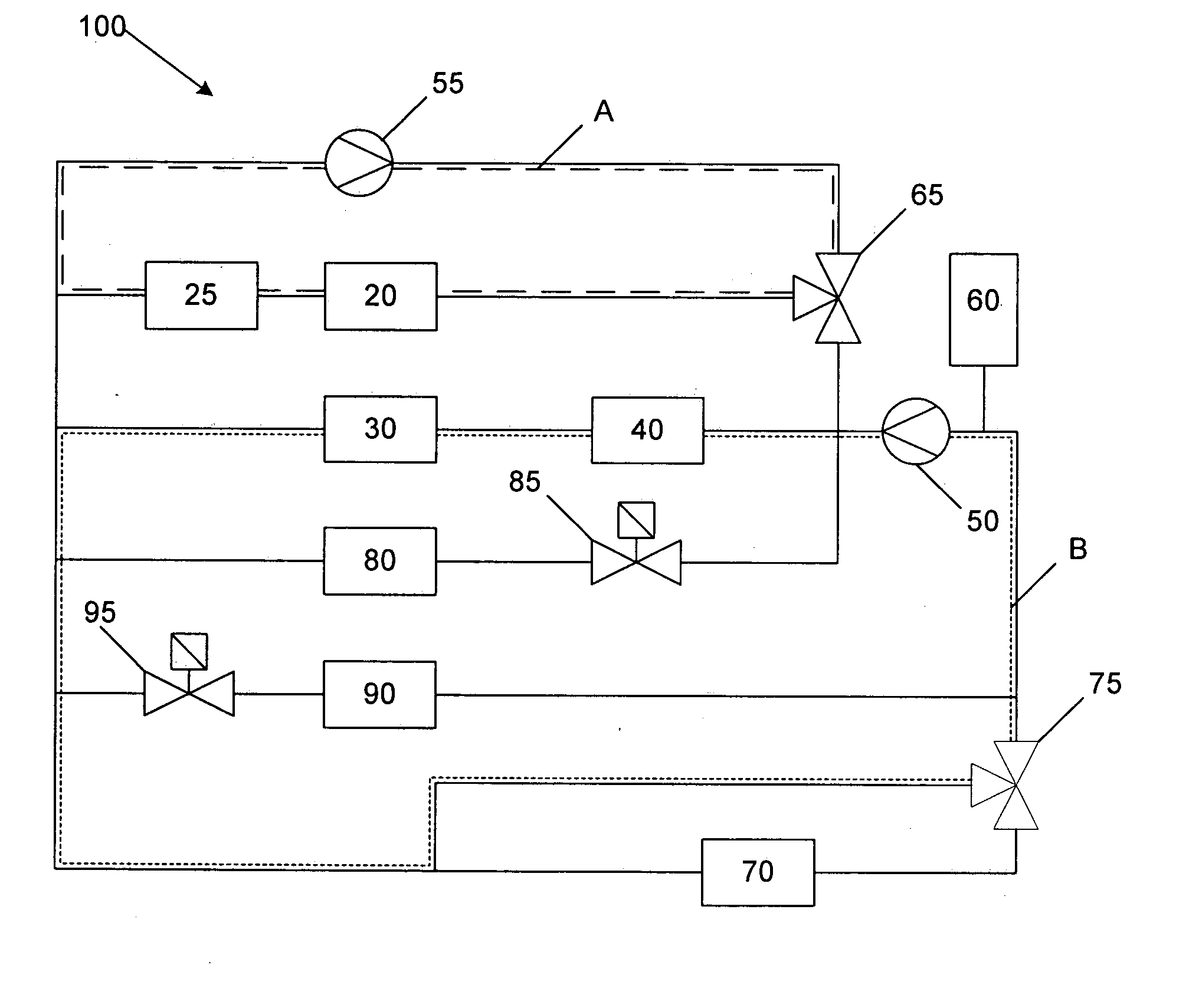
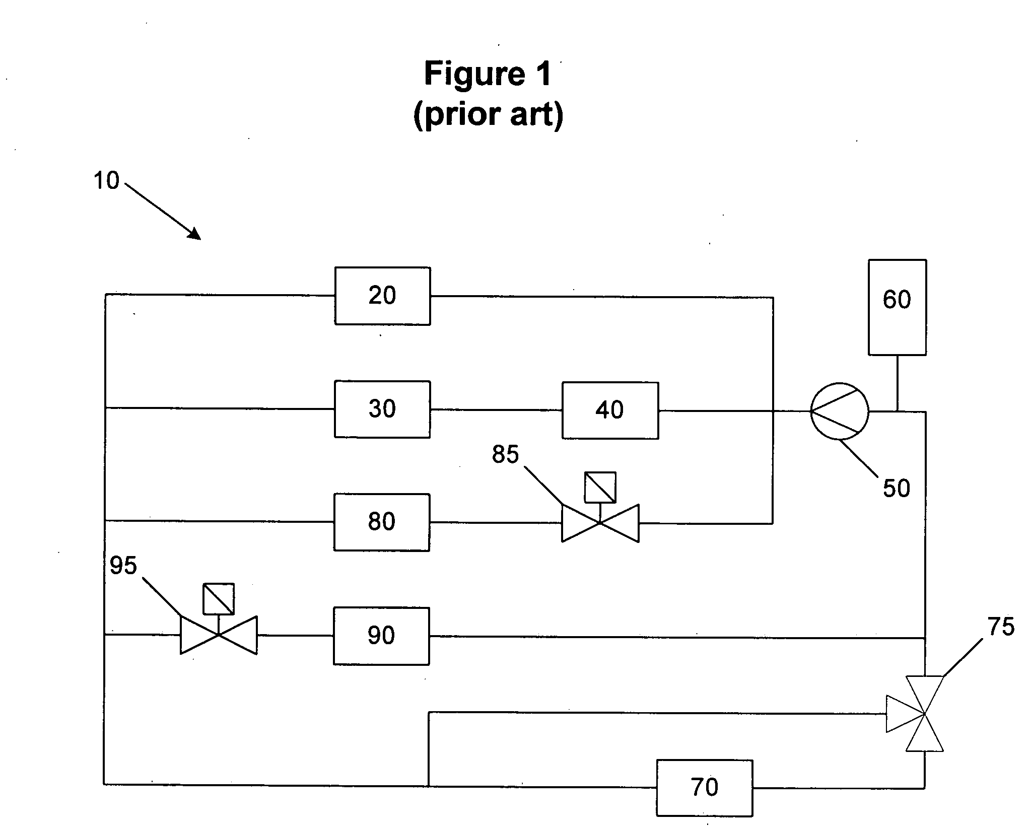
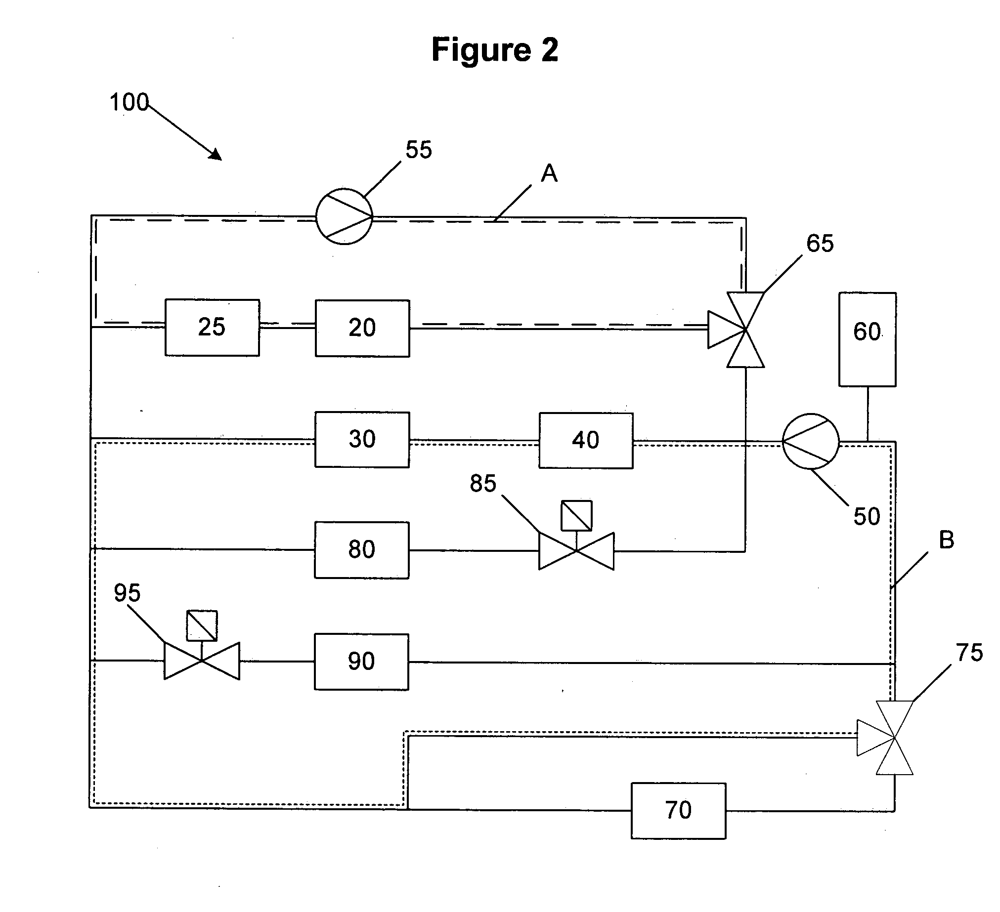
[0012] Significant improvements in start-up time from freezing or sub-freezing temperatures can be achieved by using a two pump—dual loop cooling subsystem. For example, in an electrochemical fuel cell system, the cooling subsystem may comprise both a startup coolant loop comprising a startup pump fluidly connected to the electrochemical fuel cell stack; and a standard coolant loop comprising a standard pump and a stack valve. The coolant volume of the startup coolant loop is less than the coolant volume in the standard coolant loop. During start-up, the stack valve is closed such that the electrochemical fuel cell stack is fluidly isolated from the standard coolant loop. Coolant in the startup loop circulates through the fuel cell stack and helps to quickly bring the temperature of the stack to desired temperature. If coolant did not flow through the stack, localized heating within the stack could detrimentally affect the stack. By minimizing the coolant volume in the startup loop, and in particular, by having a smaller coolant volume than in the standard coolant loop, more efficient heating can occur.
[0013] In an alternate embodiment, a cooling subsystem for an electrochemical fuel cell system may comprise a startup coolant loop fluidly connected to the electrochemical fuel cell. The startup coolant loop comprises a startup pump. The cooling subsystem also comprises a standard coolant loop comprising a standard pump and a stack valve. When the stack valve is closed, only the startup coolant loop is fluidly connected to the electrochemical fuel cell stack. However, when the stack valve is open, both the startup coolant loop and the standard coolant loop are fluidly connected to the fuel cell stack. Thus, a smaller coolant volume is available to the fuel cell stack during start-up when efficient heating is needed and a larger coolant volume is available during normal operation from both coolant loops. In a preferred embodiment, the startup coolant loop is also fluidly connected to the standard coolant loop when the stack valve is open. This is simpler to manufacture and allows the coolants to mix, thereby reducing thermal shock when the colder coolant from the standard coolant loop flows to the fuel cell stack. Nevertheless, both coolant loops could remain fluidly isolated throughout.

Problems solved by technology

If coolant did not flow through the stack, localized heating within the stack could detrimentally affect the stack.

Method used


Image

  • Cooling subsystem for an electrochemical fuel cell system
  • Cooling subsystem for an electrochemical fuel cell system
  • Cooling subsystem for an electrochemical fuel cell system

Examples


examples

[0037] A test chamber was constructed as illustrated in FIG. 4 to illustrate the effect of reduced coolant volumes on efficiency and time to bring fuel cell systems from freezing and subfreezing temperatures to normal operating temperatures. Three coolant paths were constructed, namely coolant path D, coolant path E and coolant path F. A pump 50 pumped coolant through a flow meter 35 and fuel cell stack 20 through coolant paths D and E. Coolant path E further comprises coolant reservoir 60, heater 25, and heat exchanger 45. A chilled coolant from station was directed through heat exchanger 45 as illustrated by black arrows. Coolant path E is illustrative of a conventional fuel cell system and coolant path D represents a reduced coolant volume obtained by bypassing non-essential components in a fuel cell stack though still using a one-pump system. A separate coolant path F having a stack pump 55 was used to compare the effect of a two pump system and an even smaller coolant volume du...


PUM


Abstract

Improvements in startup time for an electrochemical fuel cell system from freezing and sub-freezing temperatures may be observed by minimizing the coolant volume in the coolant subsystem. In particular, this may be accomplished by having a two pump—dual loop cooling subsystem. During startup, one pump directs coolant through a startup coolant loop and after either the fuel cell stack or the coolant temperature reaches a predetermined threshold value, coolant from a main or standard coolant loop is then directed to the fuel cell stack. In an embodiment, coolant from the standard loop mixes with coolant in the startup loop after the predetermined threshold temperature is reached.

Description

CROSS-REFERENCE TO RELATED APPLICATIONS [0001] This application relates to and claims priority benefits from provisional U.S. patent application Ser. No. 60 / 560,731 filed Feb. 9, 2004. The '731 application is incorporated herein by reference in its entirety.BACKGROUND OF THE INVENTION [0002] 1. Field of the Invention [0003] The present invention relates to electrochemical fuel cells and more particularly to subsystems and methods for controlling the temperature of a fuel cell system during startup. [0004] 2. Description of the Related Art [0005] Electrochemical fuel cells convert reactants, namely fuel and oxidant fluid streams, to generate electric power and reaction products. Electrochemical fuel cells employ an electrolyte disposed between two electrodes, namely a cathode and an anode. The electrodes each comprise an electrocatalyst disposed at the interface between the electrolyte and the electrodes to induce the desired electrochemical reactions. The location of the electrocata...

Claims


Application Information

Patent Timeline
IPC IPC(8): H01M8/04
CPCH01M8/04029Y02E60/50H01M2300/0082H01M8/04223H01M8/04225H01M8/04302
Inventor NELSON, AMY E.LIN, BRUCEROBERTS, JOY A.LIMBECK, UWE M.LOUIE, CRAIG R.BACH, PETER J.
Owner FORD MOTOR CO
Features
  • Generate Ideas
  • Intellectual Property
  • Life Sciences
  • Materials
  • Tech Scout
  • Unparalleled Data Quality
  • Higher Quality Content
  • 60% Fewer Hallucinations
Learn More