Applications for Low Profile Two Way Satellite Antenna System

Inactive Publication Date: 2011-09-08
SILICON VALLEY BANK
View PDF85 Cites 48 Cited by
  • Summary
  • Abstract
  • Description
  • Claims
  • Application Information

AI Technical Summary

Benefits of technology

[0036]In other aspects of the invention, the terminal may use modulations and forward error correction rates that permit it to radiate signals satisfying regulatory (e.g. FCC and ITU) restrictions on the power spectral density (PSD) intended to limit inter-system interference.
[0037]In other aspects of the

Problems solved by technology

The mechanically steerable reflector antenna has a relatively large volume and height, which, when enclosed in the necessary

Method used


Image

  • Applications for Low Profile Two Way Satellite Antenna System
  • Applications for Low Profile Two Way Satellite Antenna System
  • Applications for Low Profile Two Way Satellite Antenna System

Examples


Embodiment Construction

[0087]In the following description of the various embodiments, reference is made to the accompanying drawings, which form a part hereof, and in which is shown by way of illustration various embodiments in which the invention may be practiced. It is to be understood that other embodiments may be utilized and structural and functional modifications may be made without departing from the scope and spirit of the present invention.

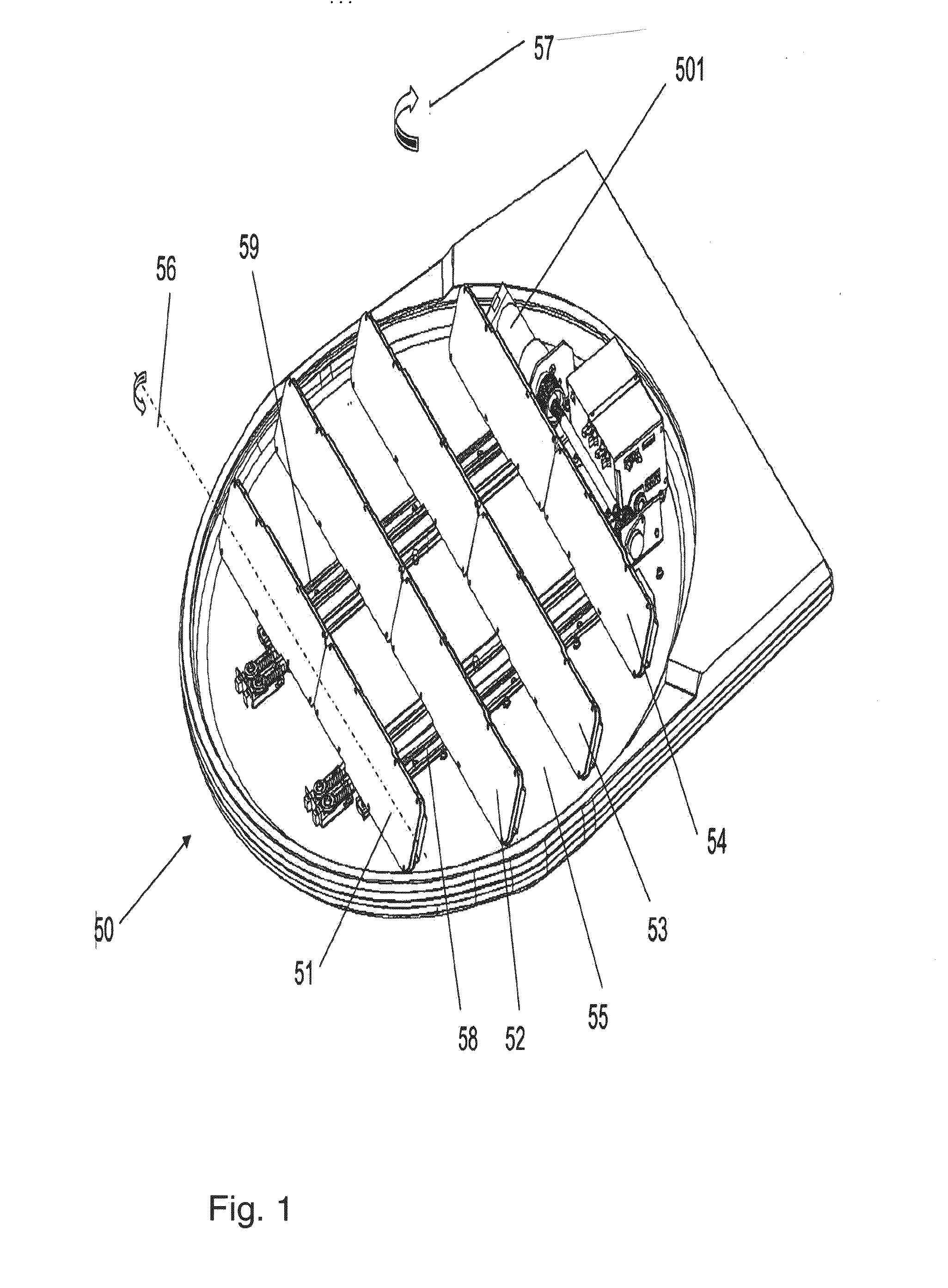
[0088]FIG. 1 illustrates a perspective view of an antenna unit 50, in accordance with an embodiment of the invention. In this exemplary embodiment, four antenna arrangements (51 to 54) may be mounted on a common rotary platform 55 using any suitable arrangement such as carriages / bearings disposed about at the center of each end of the antenna arrangement. In alternative embodiments, the antenna elements may be controlled using electronic steering such as a stepper motor, motor controller, angular rotation mechanism or other suitable arrangement. In the exemplar...


PUM


Abstract

Antenna and satellite communications assemblies and associated satellite tracking systems that may include a low profile two-way antenna arrangement, tracking systems, and applications thereof. Applications for the system include military, civilian, and domestic emergency response applications. The antenna arrangements may be configured to form a spatial multi-element array able to track a satellite in an elevation plane by electronically dynamically targeting the antenna arrangement and/or mechanically dynamically rotating the antenna arrangements about transverse axes giving rise to generation of respective elevation angles and dynamically changing the respective distances between the axes whilst maintaining a predefined relationship between said distances and the respective elevation angles. The system provides autonomous dynamic tracking of satellite signals and can be used for satellite communications on moving vehicles in a variety of frequency bands for military and civilian applications.

Description

CROSS REFERENCE TO RELATED APPLICATIONS[0001]The present application is a continuation of U.S. application Ser. No. 11 / 647,576, filed Dec. 29, 2006, which is a continuation-in-part of U.S. application Ser. No 11 / 320,805, filed Dec. 30, 2005 (now U.S. Pat. No. 7,705,793), which claims benefit under 35 USC §119(e)(1) of U.S. Provisional Application No. 60 / 650,122 filed Feb. 7, 2005, and of U.S. Provisional Application No. 60 / 653,520, filed Feb. 17, 2005, and which claims benefit under 35 USC §120 of the following United States applications in which the application is a continuation-in-part: U.S. application Ser. No. 11 / 074,754, filed Mar. 9, 2005 (now abandoned); U.S. application Ser. No. 10 / 925,937, filed Aug. 26, 2004 (now U.S. Pat. No. 7,379,707); U.S. application Ser. No. 11 / 071,440, filed Mar. 4, 2005 (now abandoned); U.S. application Ser. No. 10 / 498,668, filed Jun. 10, 2004 (now U.S. Pat. No. 6,995,712), PCT / US05 / 28507, filed Aug. 10, 2005, U.S. patent application Ser. No. 11 / 32...

Claims


Application Information

Patent Timeline
IPC IPC(8): H01Q21/08
CPCH01Q21/08H01Q3/08H01Q3/04
Inventor KAPLAN, ILANGACHEV, MARIO GANCHEVBERCOVICH, MOSHESPIRTUS, DANNYDIFONZO, DANIEL FRANCISBRUESTLE, KEVIN ARTHURYIP, ROBERTBOYANOV, VICTORGAT, YOELKAMENOPOLSKI, STANIMIR DIMITROV
Owner SILICON VALLEY BANK
Why Eureka
Try Eureka