Method and device for producing a transmission signal to be transferred over a transmission path

Active Publication Date: 2006-08-31
MAXLINEAR INC
View PDF7 Cites 1 Cited by
  • Summary
  • Abstract
  • Description
  • Claims
  • Application Information

AI Technical Summary

Benefits of technology

[0013] In another embodiment, the input signal is an xDSL signal, wherein, for example, the VDSL2 bandwidth of 30 MHz is distributed, for instance, on three frequency bands, in such a way that the lowest band range reaches up to 2.2 MHz, for which already established line drivers from the ADS environment can be re-used, the middle frequency range reached from 2.2 MHz to 17 MHz, and the highest from 17 MHz-30 MHz. This unequal frequency band distribution is advantageous, since a perceptibly higher power spectral density is usually present in the range from 1-2 MHz than in the higher fre

Problems solved by technology

The development of analogue front ends for such bandwidths is in general a considerable challenge, because the performance demands for VDSL2 are based on the same model for line noise of −140 dBm/Hz, as is used for narrower bandwidths such as ADSL (1.1 MHz, ADSL2+(2.2 MHz), SHDSL (600 kHz) (“Symmetric High-bitrate DSL”) or VDSLI (12 MHz).
This means that a large bandwidth and good linearity represent a conflict of aims.
A similar problem arises with the PAR property of a line driver.
The increased feed voltage, however, results in the undesirable disadvantage of an increased PAR.
Despite substantially improved performance features, however, there are a series of substantial disadvantages.
In addition to this, filters of a higher order have a not insubstantial pass attenuation and disadvantageous inductivity and capacitance tolerances, which leads to a deterioration of the performance features.
Filters of a higher order also cause a greater inter-symbol interference.
In this situation, highe

Method used


Image

  • Method and device for producing a transmission signal to be transferred over a transmission path
  • Method and device for producing a transmission signal to be transferred over a transmission path
  • Method and device for producing a transmission signal to be transferred over a transmission path

Examples


Embodiment Construction

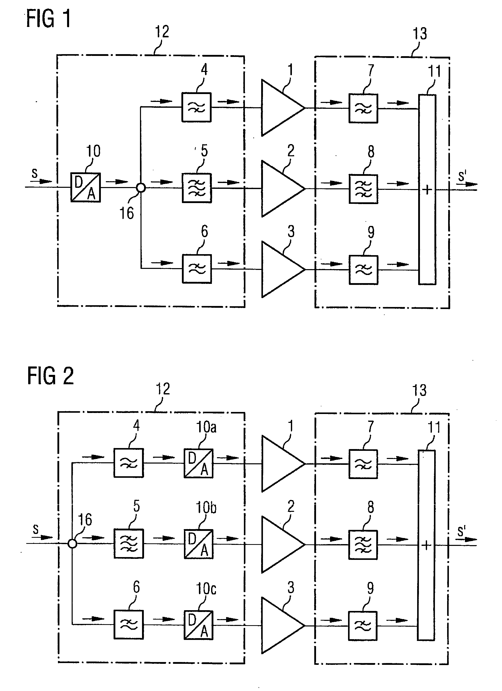
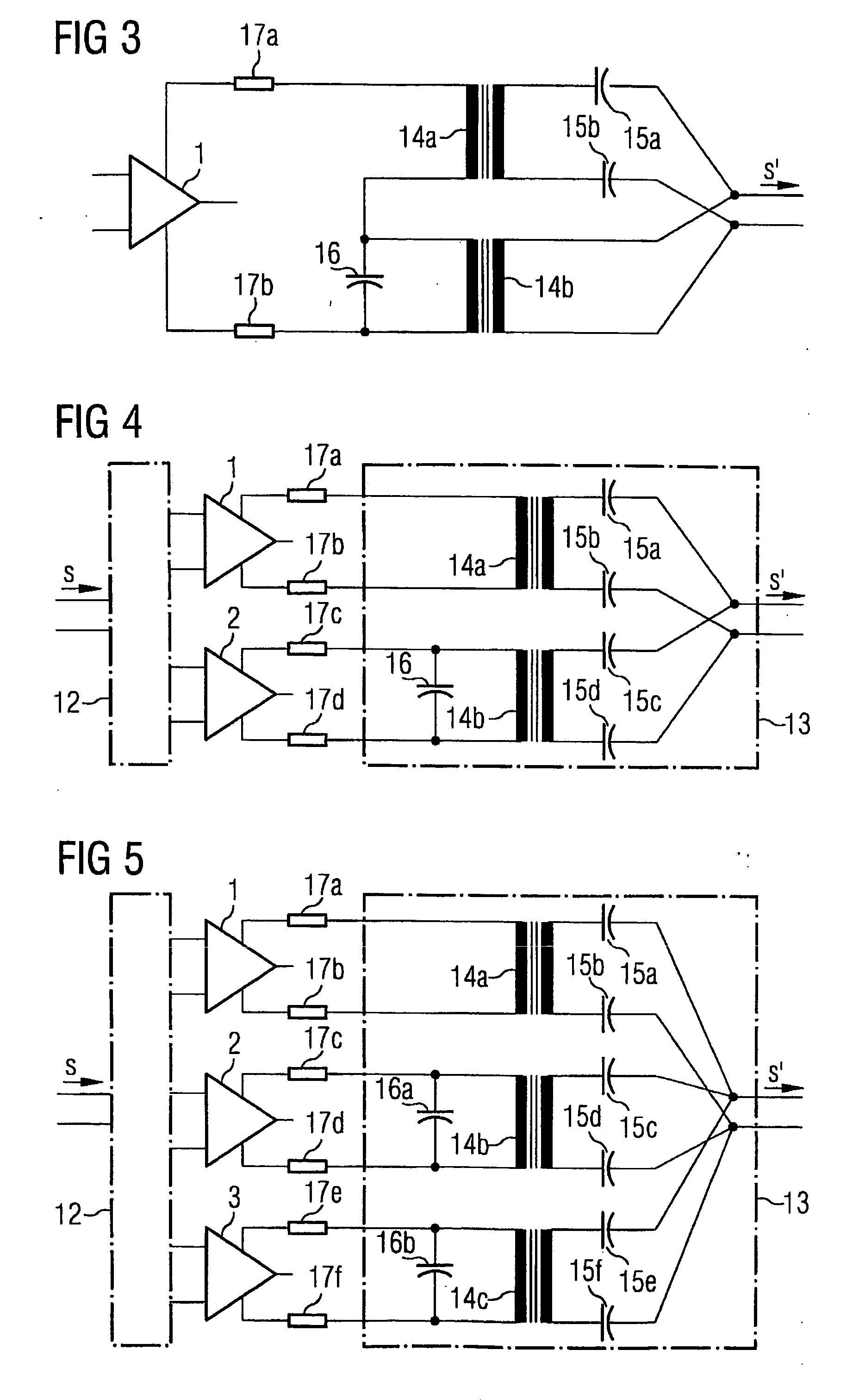
[0023] Hereinafter a number of embodiments of the present invention are described in greater detail on the basis of the drawings.

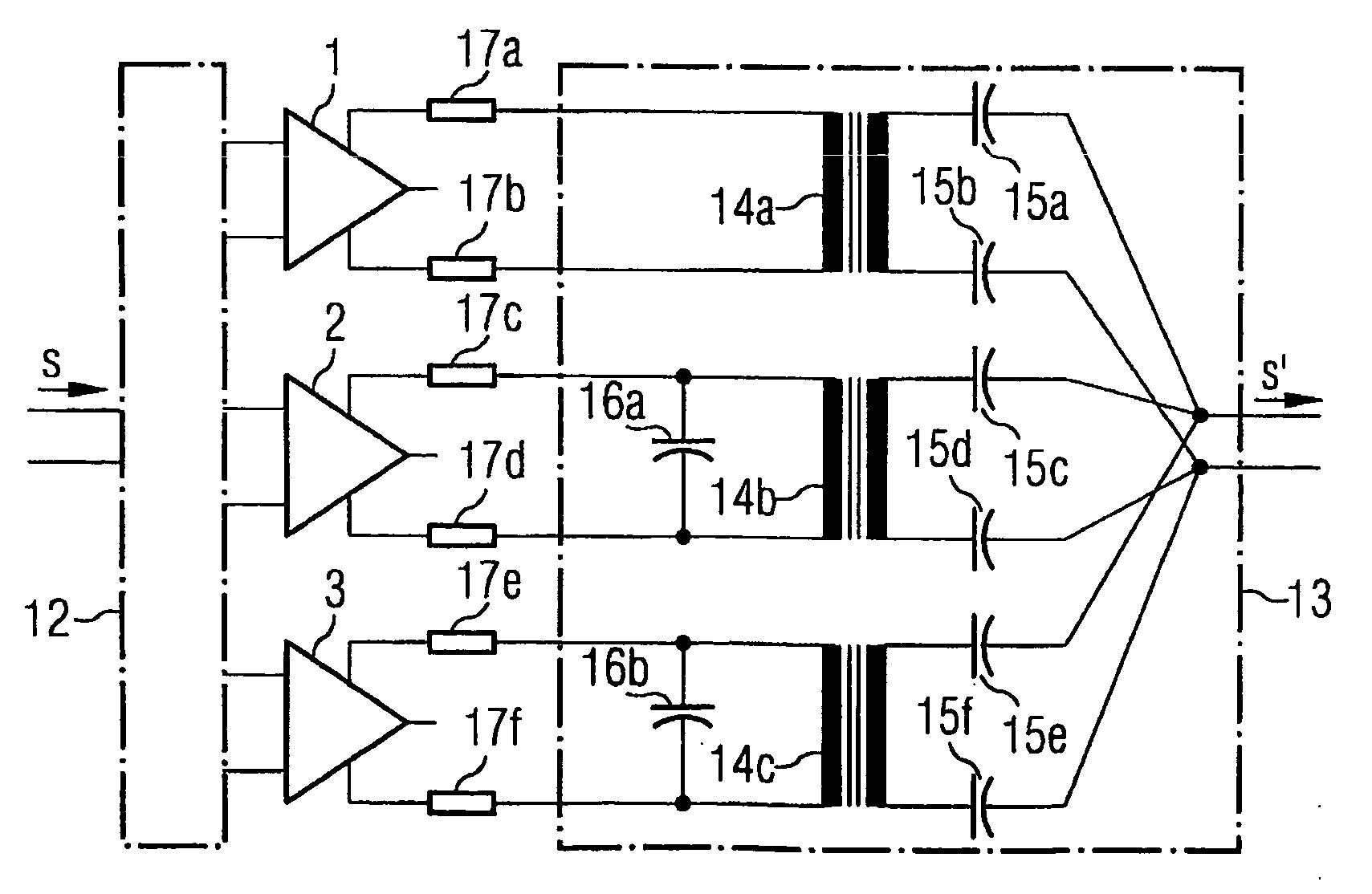
[0024] In FIG. 1 an embodiment is shown with three line driver paths, in which in each case a line driver 1-3 is arranged. An xDSL input signal s is transformed in a D / A converter 10 into an analogue signal, which is branched at a node 16 onto the three line driver paths. A filter means 4 is designed as a high-pass, as a result of which the line driver 1 only receives the high-frequency signal parts of the input signal s, amplifies these, and conducts them onwards on the output side into a further filter means 7, which is designed as a further high-pass. A filter means 5 is designed as a band pass, as a result of which the line driver 2 only receives signal parts of the input signal s from a frequency band delimited upwards and downwards, amplifies these, and conducts them onwards on the output side into a further filter means 8, which is designed as a ba...


PUM


Abstract

A method and device are provided for producing a transmission signal to be transferred over a transmission path from an input signal, for example an xDSL signal, wherein a bandwidth of the input signal is distributed onto a plurality of frequency bands in such a way that part signals are obtained corresponding to the individual frequency bands, and wherein each part signal is conducted to separate line drivers, and wherein output signals of the individual line drivers are combined to form the transmission signal to be transferred over the transmission path by combination means, which can be designed as an adder. In order to obtain the frequency band which pertains in each case from the input signal, which can be transformed into an analogue signal with a D/A converter, filter means can be used.

Description

FIELD OF THE INVENTION [0001] The present invention relates to a method and device for producing a transmission signal to be transferred over a transmission path, which in this case is processed by means of line drivers. In particular, the invention relates to a device and a method of this kind for producing an xDSL transmission signal (“Digital Subscriber Line”). BACKGROUND [0002] The development of the DSL technique is oriented towards a constantly rising signal bandwidth. With the VDSL2 (“Very high-speed DSL”) standardisation process, a maximum transmission bandwidth of 30 MHz is provided. The development of analogue front ends for such bandwidths is in general a considerable challenge, because the performance demands for VDSL2 are based on the same model for line noise of −140 dBm / Hz, as is used for narrower bandwidths such as ADSL (1.1 MHz, ADSL2+(2.2 MHz), SHDSL (600 kHz) (“Symmetric High-bitrate DSL”) or VDSLI (12 MHz). In this situation, there is particular emphasis on line ...

Claims


Application Information

Patent Timeline
IPC IPC(8): H04B3/00
CPCH04L25/028H04L25/14
Inventor STOLLE, REINHARD
Owner MAXLINEAR INC
Why Eureka
Try Eureka