Apparatus and method for motion vector filtering based on local image segmentation and lattice maps

a local image segmentation and lattice map technology, applied in image enhancement, instruments, television systems, etc., can solve the problems of motion vector field errors, near impossible to eliminate, and difficult to elimina

Inactive Publication Date: 2011-09-08
QUALCOMM INC
View PDF21 Cites 7 Cited by
  • Summary
  • Abstract
  • Description
  • Claims
  • Application Information

AI Technical Summary

Benefits of technology

[0007]A method of filtering a motion vector field provided by a motion estimation apparatus is disclosed. The method includes receiving an input image and a delayed image, determining a motion vector field associated with the input image, determining a local segmentation image, forming a lattice map to identify periodic structures in the image, using the local segmentation image and the lattice map to obtain an image segment pixel count and an image/motion segment pixel count, and using the segment pixel count and the image/motion segment pixel count to provide a filtered motion vector field. Some embodiments of the present invention further include a motion estimation apparatus including an image delay apparatus to provide a delayed image from an input image, a lattice detector to find lattice structures in the input image and the delayed image and provide a lattice map, a histogram generator and a histogram analyzer to provide a set of horizontal

Problems solved by technology

Motion estimation (ME) methods using exhaustive full-search block-matching techniques are prone to errors in the motion vector fields.
These errors may come from different types of content in a source and are nearly impossible to eliminate without applying some extra processing steps on the motion vector fields.
Some motion vector errors can occur in groups where all neighboring motion vectors are similar, but all erroneous.
These regions within the motion vector field are harder to fil

Method used


Image

  • Apparatus and method for motion vector filtering based on local image segmentation and lattice maps
  • Apparatus and method for motion vector filtering based on local image segmentation and lattice maps
  • Apparatus and method for motion vector filtering based on local image segmentation and lattice maps

Examples


Embodiment Construction

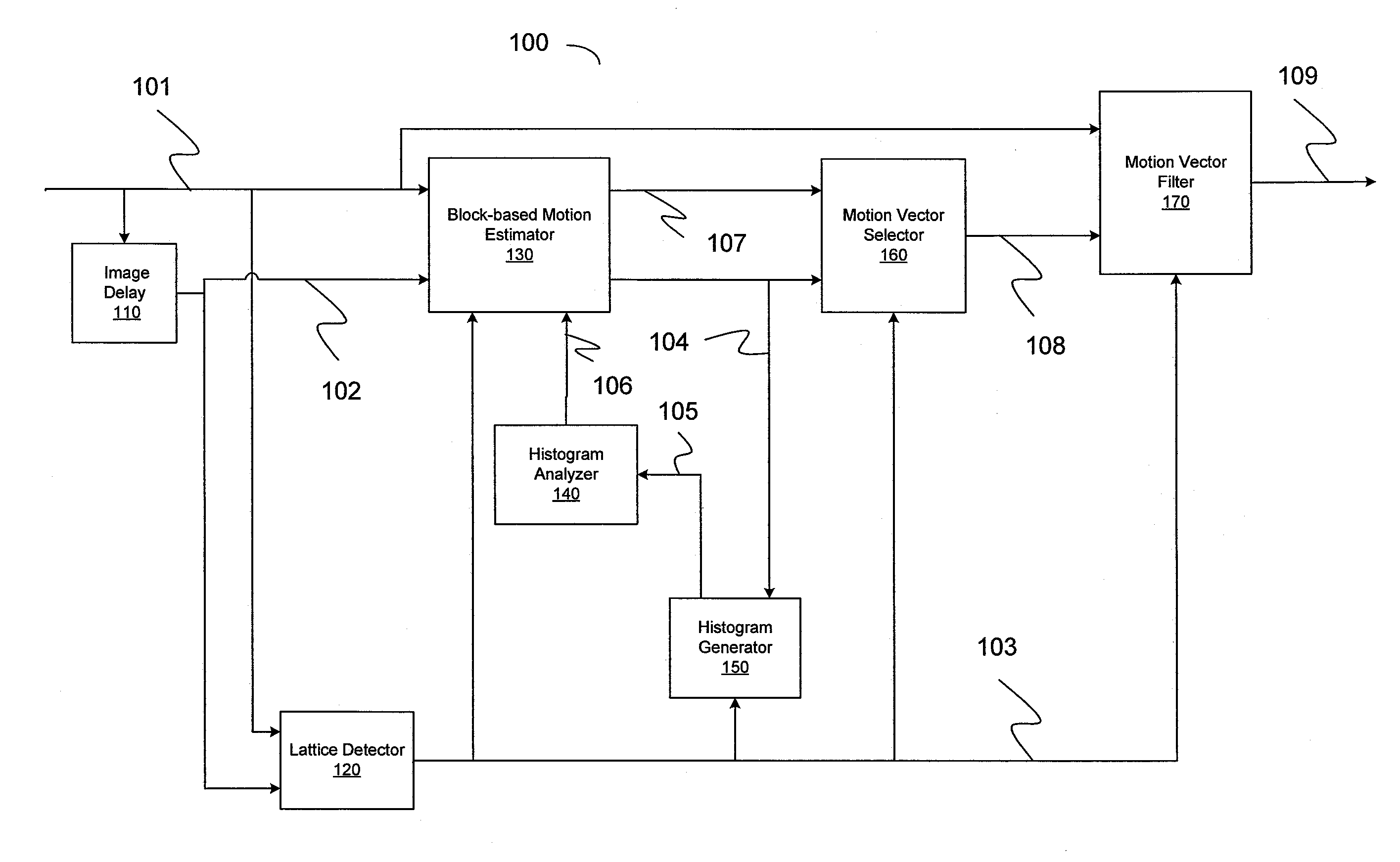
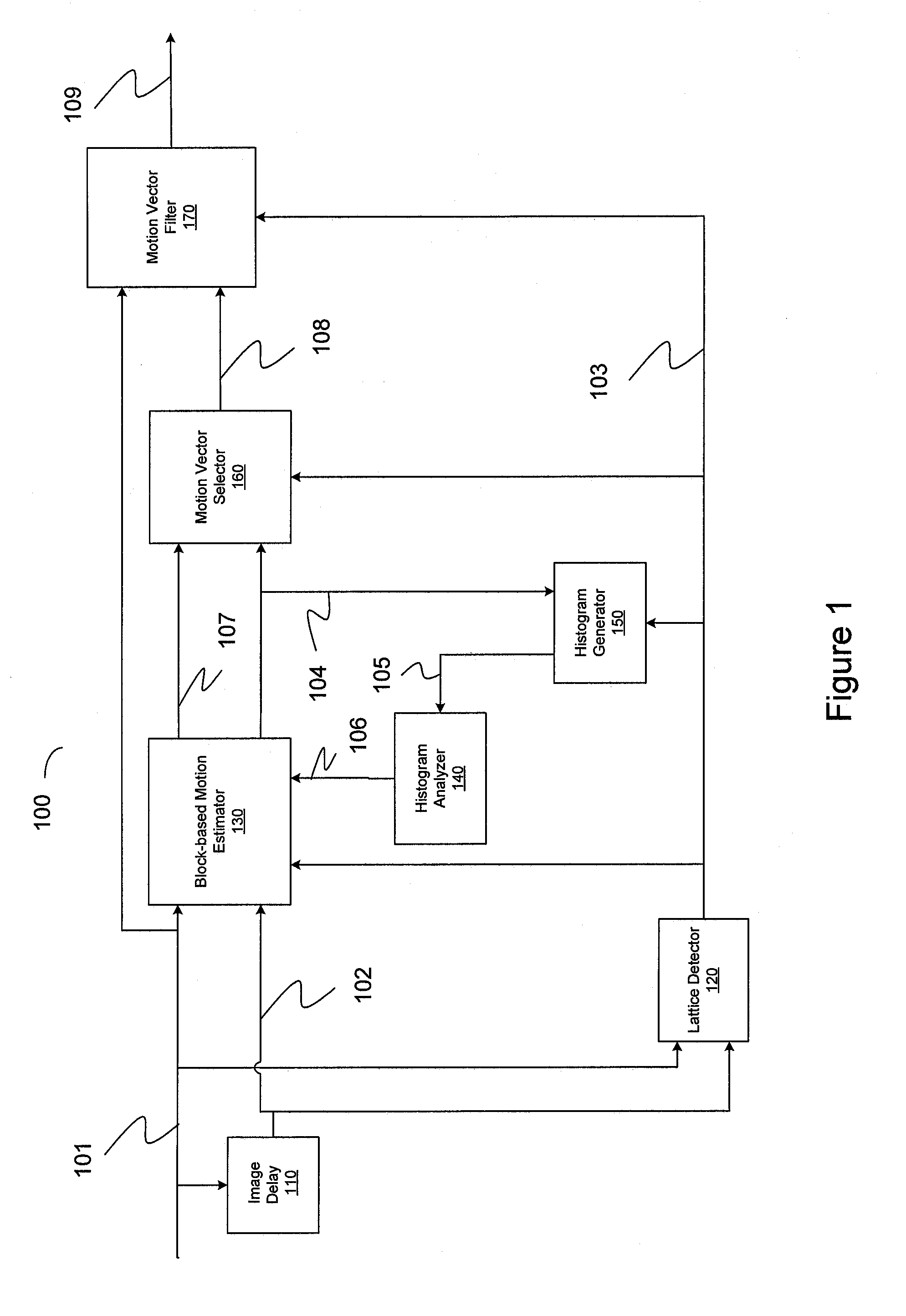
[0016]Many apparatuses and methods have been developed to filter motion vector fields using different approaches. In some apparatuses, a ME apparatus may not use a motion vector filter. Either the filtering or smoothing effect is intrinsic to the ME or a minor internal filtering operation takes place in the ME such as temporal loop filtering. These methods may access error calculations from the block matching process; thus a set of candidate motion vectors may be ‘checked’ or tested prior to a selection. However, these steps are computationally extensive and may overload the computational capabilities of the apparatus for large and complex image frames. Some embodiments of the invention as is further described below relate to an apparatus and methods of motion vector filtering which are independent of the ME apparatus itself, and operate as a stand-alone post-processing apparatus. Further, some embodiments of the invention may not require computationally extensive error calculations...


PUM


Abstract

A method and an apparatus for filtering motion vector fields provided by a motion estimator apparatus are disclosed. The method includes receiving an input image, determining a motion vector field associated with the input image, determining a local segmentation image, forming a lattice map to identify periodic structures, using the local segmentation image and the lattice map to obtain an image segment pixel count and an image/motion segment pixel count, and using the segment pixel count and the image/motion segment pixel count to provide a filtered motion vector field. Some embodiments further include a motion estimation apparatus including an image delay apparatus, a lattice detector to find lattice structures in the input and delayed images, a histogram generator and a histogram analyzer to provide a set of horizontal and vertical search masks, a motion vector estimator to provide a motion vector field, and a motion vector filter as provided herein.

Description

BACKGROUND[0001]1. Field of the Invention[0002]This invention relates to the fields of video compression and motion-compensated image interpolation for frame-rate conversion, and, more particularly, to an apparatus and methods for filtering motion vectors provided by block-based motion estimation (ME) apparatuses and methods.[0003]2. Description of Related Art[0004]Many image and video processing apparatuses and methods, such as motion-compensated image interpolation, rely on estimated motion vectors. Typically these motion vectors are block-based, in which a motion vector represents a rectangular group of pixels. In some apparatuses and methods, such as image interpolation, it is important that these motion vectors be ‘true’, that is substantially free of any errors, so as not to produce any processing artifacts in the output results. Motion estimation (ME) methods using exhaustive full-search block-matching techniques are prone to errors in the motion vector fields. These errors m...

Claims


Application Information

Patent Timeline
IPC IPC(8): H04N7/32
CPCH04N19/50G06T2207/10016G06T2207/20021
Inventor ROSSIGNOL, FRANCOISTRAN, THI THUY-HALEDINH, CHON TAM
Owner QUALCOMM INC
Why Eureka
Try Eureka