Virtual surround for loudspeakers with increased constant directivity

a virtual surround and constant directivity technology, applied in the direction of electrical transducers, stereophonic arrangments, transducer details, etc., can solve the problems of difficult to properly implement higher frequencies with a dipole beamforming array, difference in phase between ears, and time difference, so as to increase the sense of spaciousness, increase the sense of space, and increase the apparent source width

Active Publication Date: 2011-09-08
LOGITECH EURO SA
View PDF78 Cites 31 Cited by
  • Summary
  • Abstract
  • Description
  • Claims
  • Application Information

AI Technical Summary

Benefits of technology

[0010]Various embodiments provide virtual surround with only 1 or 2 enclosures that can be placed in front of the listener. These embodiments also have substantially constant directivity across a range of frequencies. Various embodiments accomplish this by combining techniques that can be effective at different frequency ranges. For example, some embodiments combine dipole beamforming with pointing transducers to the side (i.e., away from the listening area). Pointing a transducer to the side provides directionality due to transducer beaming at higher frequencies. Additional directionality from “shading” can occur when the sound is shaded by the edge of the speaker box. Sound from the side firing transducers that is reflected off nearby objects or walls can also increase the sense of spaciousness, listener envelopment, and the apparent source width.

Problems solved by technology

This can cause a difference in time and therefore a difference in phase between the ears.
However, higher frequencies can be difficult to properly implement with a dipole beamforming array because higher frequencies have smaller wavelengths, and it may not always be physically possible to place tweeters (or other transducers) close enough together for an optimized dipole beamforming system.
This may result in the woofer playing outside its omnidirectional frequency range, but the off-axis roll-off of the woofer at higher frequencies may be a minor effect compared to the lobing resulting from using an array outside the usable frequency region.

Method used


Image

  • Virtual surround for loudspeakers with increased constant directivity
  • Virtual surround for loudspeakers with increased constant directivity
  • Virtual surround for loudspeakers with increased constant directivity

Examples


Embodiment Construction

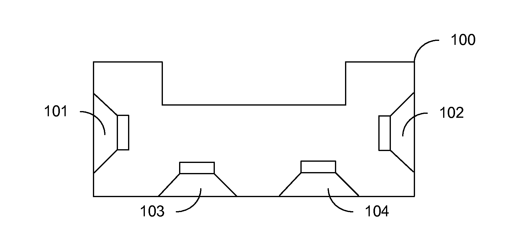
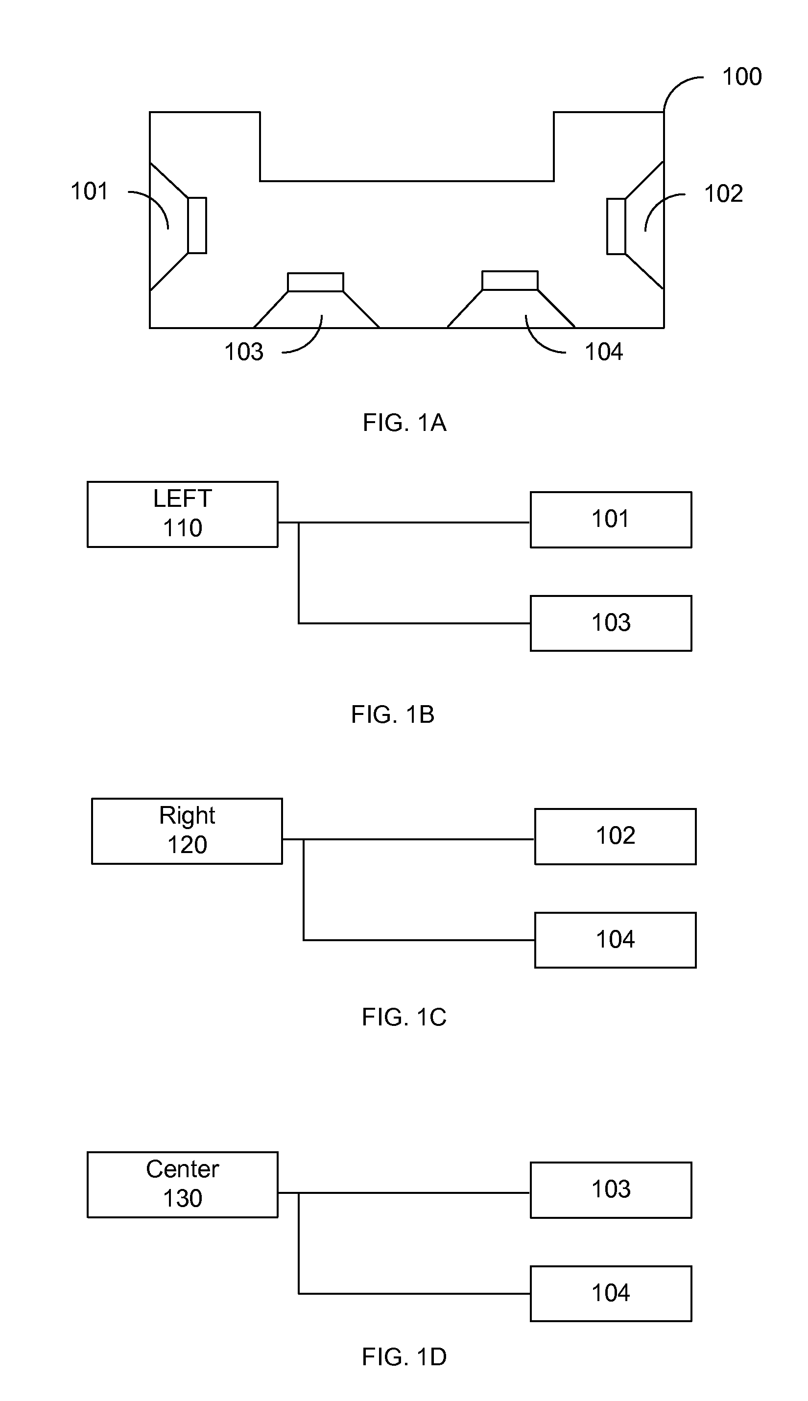
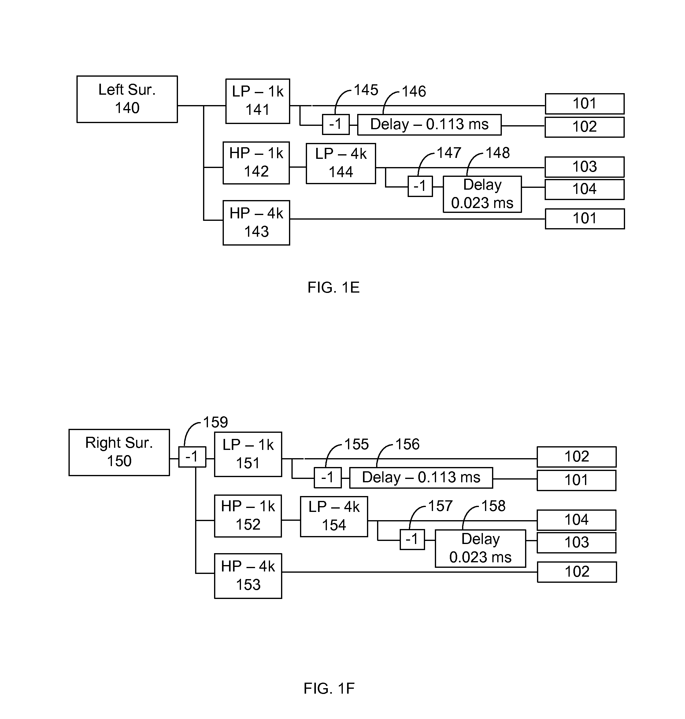
[0030]Various embodiments use combinations of different methods for creating virtual surround. Some of the methods used in various embodiments include: dipole beamforming, multi-stage arrays, transducer directionality, and enclosure shading. In general, each of these methods may operate over a specific frequency band in various embodiments. The use of multiple methods to create virtual sound can increase the virtual sound effect and better maintain sound quality compared to the use of a single method for creating virtual surround. Each method used to create virtual surround can be optimized for a specific system configuration based on factors such as physical locations of the transducers, directionality of the transducers, the size and shape of the enclosure, and the input signal configuration. Various embodiments allow for an intensity difference to be created for a listener across a wide range of frequencies in order to produce constant directionality.

[0031]As used herein, a “tran...


PUM


Abstract

A speaker system includes a first array of transducers in a speaker enclosure and, and at least a second array of transducers in the speaker enclosure. The second array is a low-frequency array and the first array is a high-frequency array. The transducers in the first array are configured to have an operating frequency region covering at least the frequency ranges of the first array and the second array, and the transducers in the second are configured to have an operating frequency region covering at least the frequency ranges of the first array and the second array. The speaker system further includes an input port, and a controller operatively coupled with the input port. The controller is configured to provide an electronic-audio signal to the transducers such that the first array and the second array are tuned to different center frequencies and are a two stage dipole beamforming array.

Description

CROSS REFERENCE TO RELATED APPLICATION[0001]This application is a continuation-in-part application of U.S. patent application Ser. No. 12 / 717,781, filed Mar. 4, 2010, titled “VIRTUAL SURROUND FOR LOUDSPEAKERS WITH INCREASED CONSTANT DIRECTIVITY,” of Jason Riggs et al., and is incorporated by reference herein in its entirety for all purposes.BACKGROUND OF THE INVENTION[0002]In traditional surround sound systems, a listener places 5 or more speakers at various positions around a listening position (sometimes also referred to as a listening area) to create an immersive sound experience for a listener. Each of the speakers in the system typically receives its own audio signal from an audio source, and consequently, the listener typically must wire each of the speakers to the audio source. The speakers in the audio system then produce sound that converges at the listening position to properly create a surround sound experience for the listener.[0003]Virtual surround is a surround sound t...

Claims


Application Information

Patent Timeline
Patent Type & Authority Applications(United States)
IPC IPC(8): H04R5/02
CPCH04R5/02H04R1/403H04R1/26H04R3/12H04R2201/401H04R2203/12H04R1/24H04R2205/022H04R2201/403H04R3/14
Inventor RIGGS, JASONLINSE, JASON N.HU, RONGLYONS, JOY E.
Owner LOGITECH EURO SA
Why Eureka
Try Eureka