Grinding machine having the function of measuring distance

a technology of grinding machine and measuring distance, which is applied in the direction of metal-working equipment, automatic grinding control, manufacturing tools, etc., can solve the problems of damage to workpieces by grinding wheels, and achieve the highest degree of sharpness, accurately and quickly

Active Publication Date: 2011-09-08
TOSHIBA MASCH CO LTD
View PDF10 Cites 12 Cited by
  • Summary
  • Abstract
  • Description
  • Claims
  • Application Information

AI Technical Summary

Benefits of technology

[0021]Alternatively, preferably, the microscope is vertically moved; a plurality of images viewed through the vertically moving microscope during the first moving travel are continuously received at predetermined time intervals; an image with the highest degree of sharpness is specified based on the sharpness of each image received; a vertical region including the vertical position corresponding to the image with the highest degree of sharpness is extracted; a plurality of images viewed through the vertically moving microscope during the second moving travel for the extracted vertical region are continuously received at predetermined time intervals; and an image with the highest degree of sharpness is specified based on the sharpness of each image received, thereby measuring the vertical distance between the reference plane of the microscope and the object of the microscope. According to this manner, the vertical distance between the reference plane of the microscope and the object of the microscope can be measured semi-automatically, accurately and quickly.

Problems solved by technology

The above-described manner that a grinding wheel is manually brought into contact with a workpiece, however, has a problem that the grinding wheel may damage the workpiece when it comes into contact with the workpiece.
The aforementioned second manner that a grinding wheel is automatically brought into contact with a workpiece also has a problem that it can be used only when both the grinding wheel and the workpiece are electrically conductive.

Method used


Image

  • Grinding machine having the function of measuring distance
  • Grinding machine having the function of measuring distance
  • Grinding machine having the function of measuring distance

Examples


Embodiment Construction

[0031]With reference to the accompanying drawings, an embodiment of the present invention will be described hereinafter.

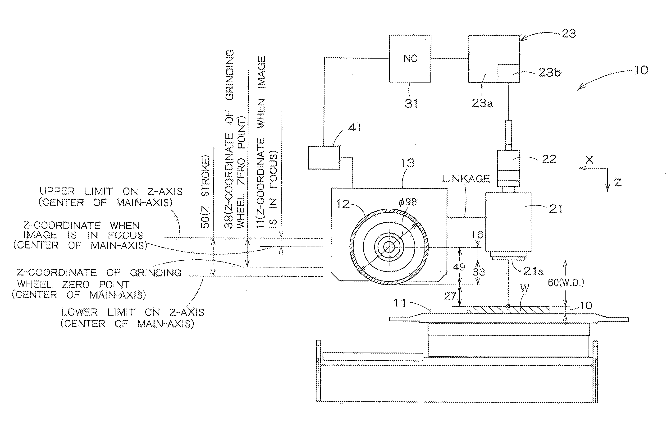
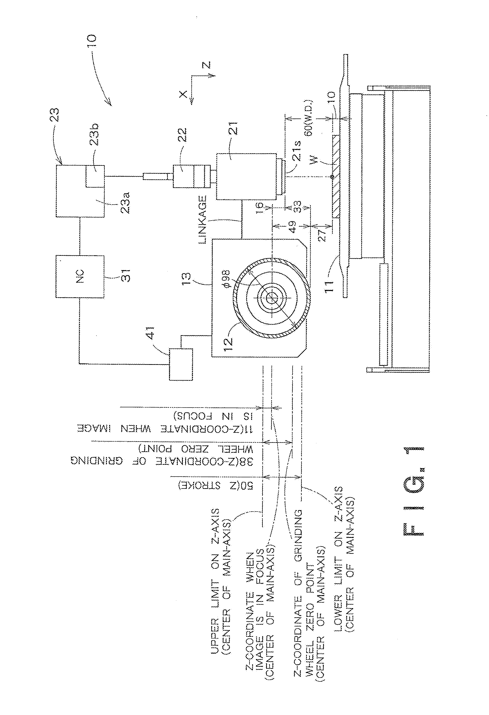
[0032]FIG. 1 is a diagrammatic view of a grinding machine having the function of measuring a vertical distance between a reference plane of a microscope and an object of the microscope according to an embodiment of the present invention. As shown in FIG. 1, a grinding machine 10 according to this embodiment includes a chuck top surface 11, on which a workpiece W is to be set. The chuck top surface 11 is movable in the X direction (the right-and-left direction on the plane of FIG. 1) and in the Y direction (in the direction vertical to the plane of FIG. 1) within the same horizontal level. Moreover, the top chuck surface 11 is rotatable around a rotational axis thereof, not shown in FIG. 1, on the X-Y plane (the top chuck surface 11 has the degree of freedom “R”).

[0033]The grinding machine 10 according to this embodiment comprises a rotating grinding wheel 12, and t...


PUM


Abstract

The invention relates to a grinding machine for grinding a workpiece, which has been set on a chuck top surface, by moving a rotating grinding wheel in relation to the workpiece. The grinding machine includes: a microscope configured to be vertically movable; a CCD camera configured to take an image viewed through the microscope; and an image processor configured to process the image taken by the CCD camera to measure a vertical distance between a reference plane of the microscope and an object of the microscope. The image processor is adapted to measure the vertical distance between the reference plane of the microscope and the object of the microscope based on sharpness of the image, which corresponds to how clear the microscope is focused.

Description

CROSS REFERENCE TO RELATED APPLICATIONS[0001]This application is based upon and claims the benefit of priority from the prior Japanese Patent Application No. 2010-49407 filed on Mar. 5, 2010, the entire contents of which are incorporated herein by reference.FIELD OF THE INVENTION[0002]The present invention relates to a grinding machine for grinding a workpiece, which is set on a chuck top surface, by moving a rotating grinding wheel in relation to the workpiece. More particularly, the present invention relates to a grinding machine having the function of measuring the vertical distance between a grinding wheel and a workpiece or the like.BACKGROUND ART[0003]There have widely been known grinding machines for grinding workpieces, which are set on respective chuck top surfaces, by moving rotating respective grinding wheels in relation to the workpieces. In such a conventional grinding machine, a very-slowly rotating grinding wheel is brought into contact with a workpiece by gradually l...

Claims


Application Information

Patent Timeline
Patent Type & Authority Applications(United States)
IPC IPC(8): B24B49/12
CPCB24B49/12B24B47/10
Inventor AKIYAMA, TAKANOBUKAKISHIMA, HIROYUKI
Owner TOSHIBA MASCH CO LTD
Why Eureka
Try Eureka