

Formation fluid property determination
a technology of fluid properties and fluids, applied in seismology for waterlogging, instruments, borehole/well accessories, etc., can solve the problems of insufficient improvement of sample quality, high cost of downhole sampling,
- Summary
- Abstract
- Description
- Claims
- Application Information
AI Technical Summary
Problems solved by technology
Method used
Image

Examples
Embodiment Construction
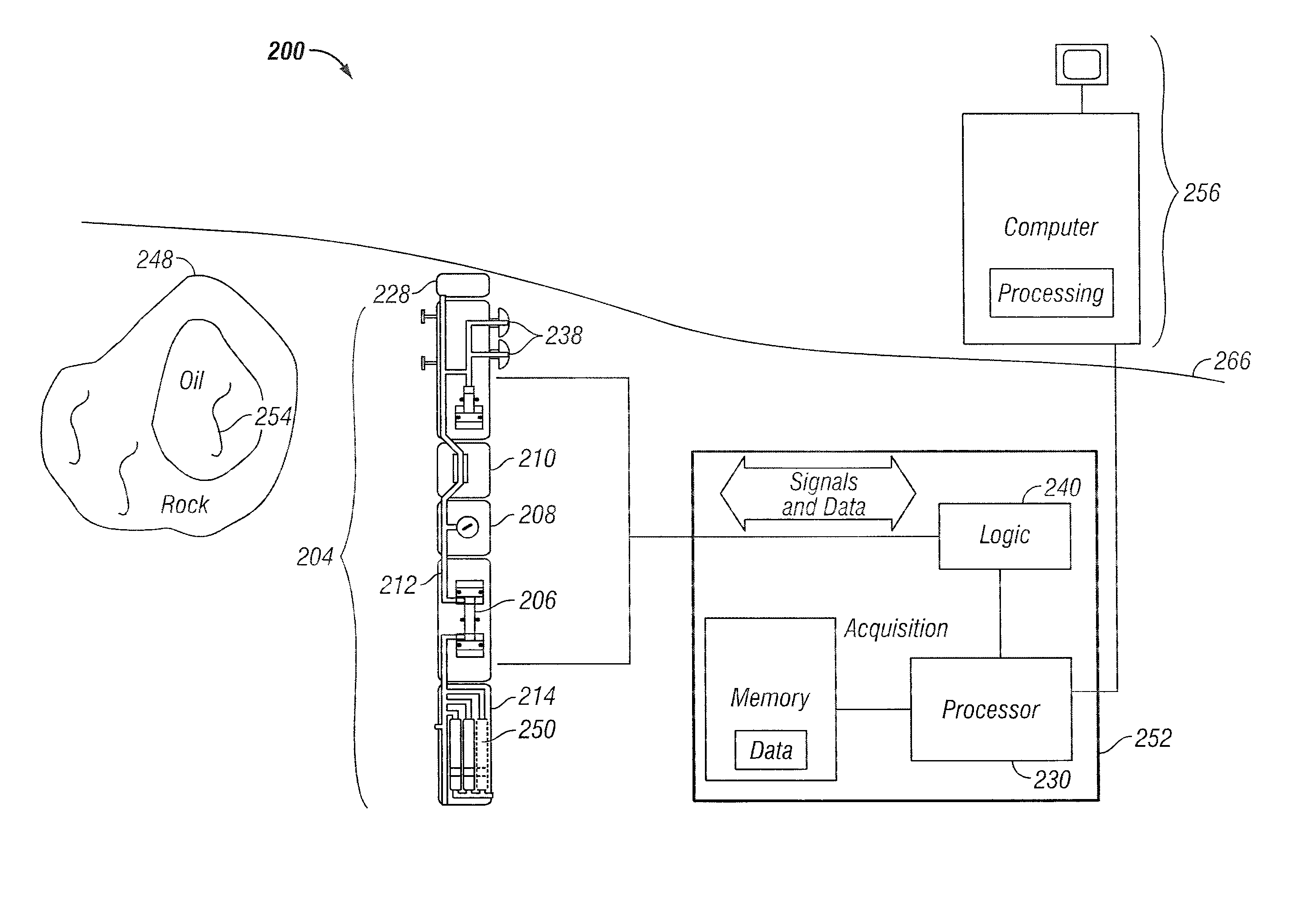
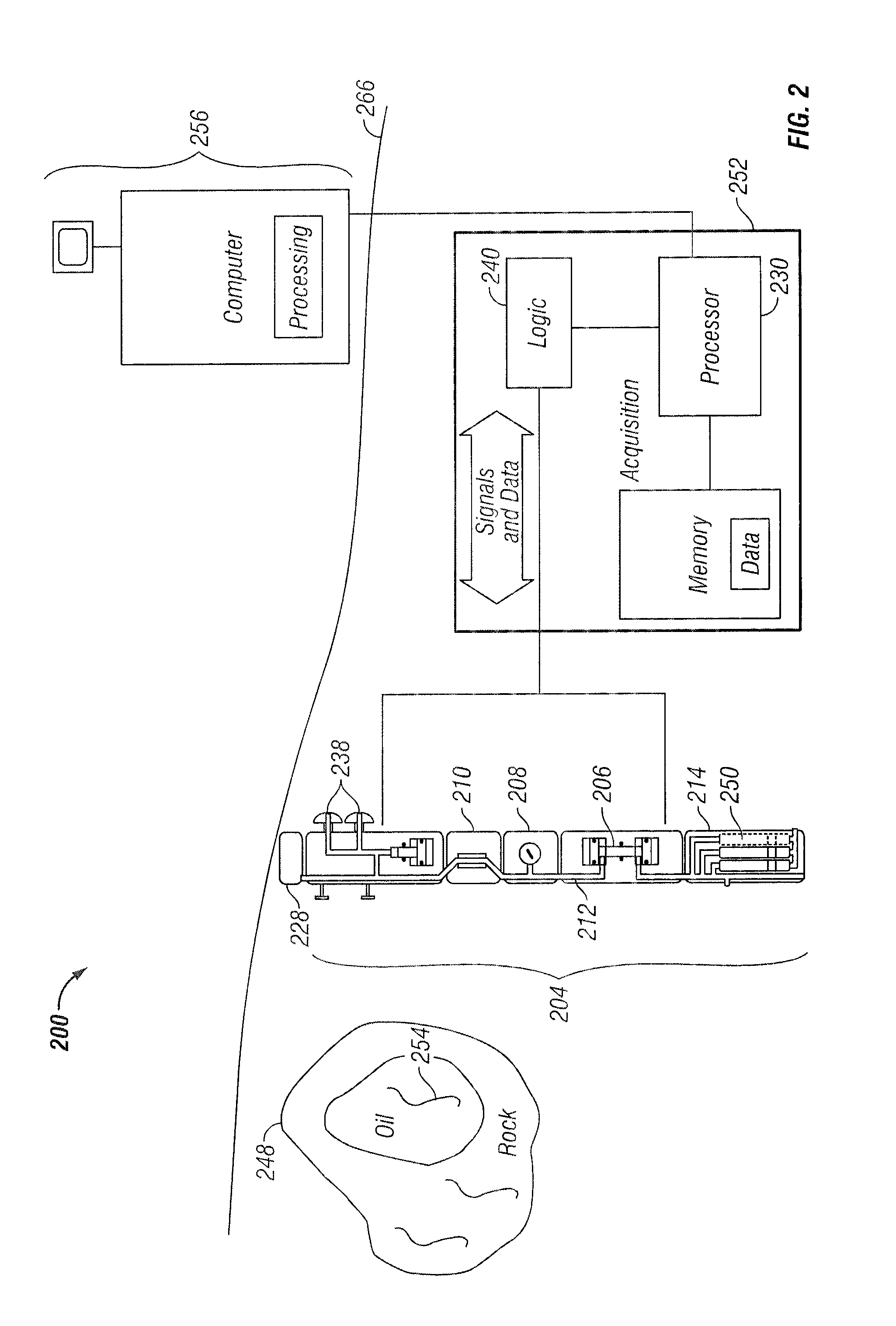
[0009]The current generation of formation evaluation tools draw fluid samples from formations through the mud cake of a well bore. This fluid is then transported through sensors within the tool, perhaps through a pump and / or another set of sensors, and finally past a sampling valve for capture. Many sensing methods are available to determine the fluid properties, including optical properties, physical properties (e.g., viscosity, density), nuclear magnetic resonance properties, etc. Using the various techniques presented herein, these properties can be used to predict when a sufficiently clean sample can been taken.
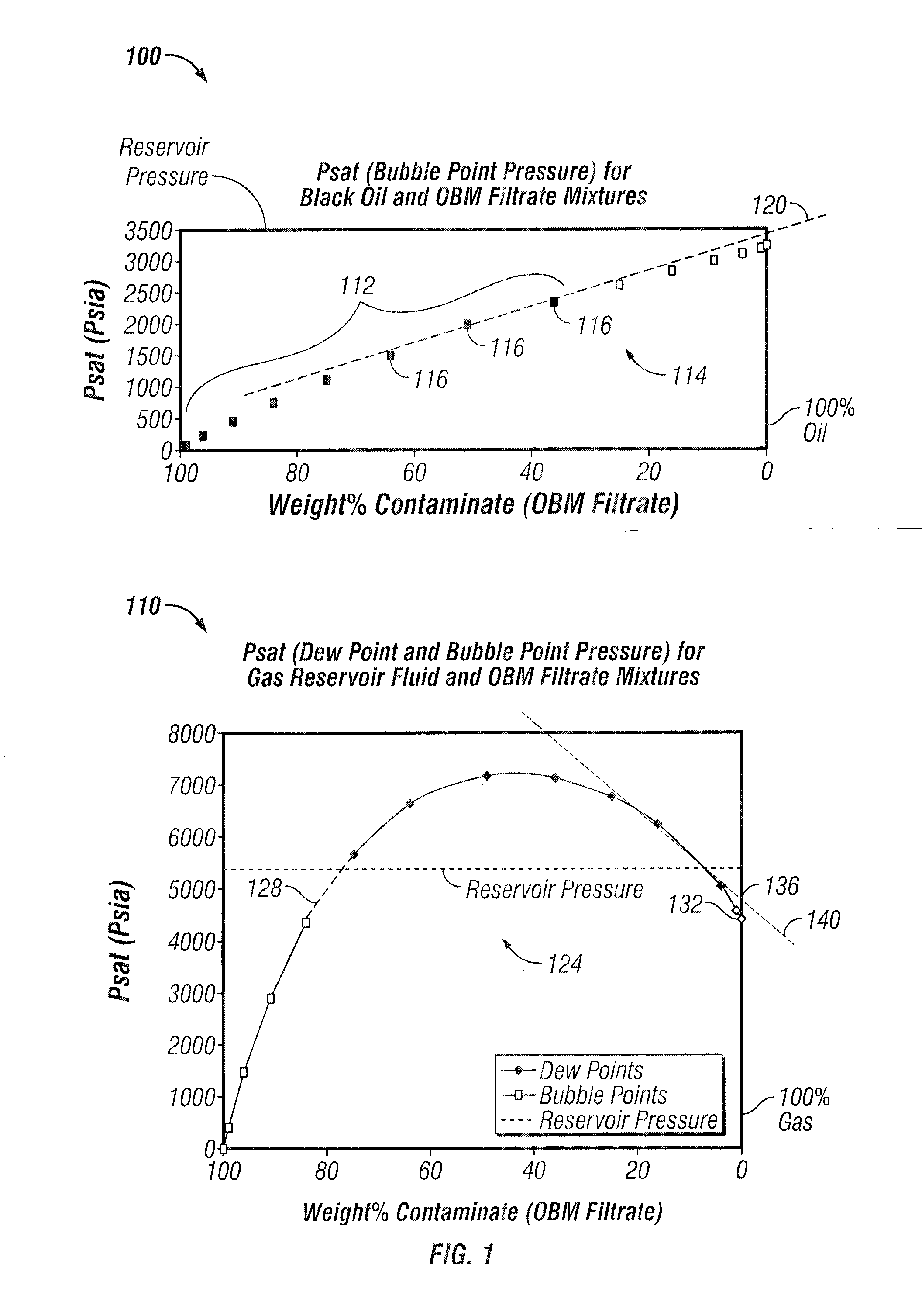
[0010]For example, a method of predicting fluid sample contamination may involve using one or more measured properties of the fluid, such as saturation pressure, which has a response to fluid composition that is substantially linear, or can be approximated as linear over a defined sampling interval. The selected fluid property can then be measured at a series of specific ...
PUM
 Abstract
Description
Claims
Application Information