
Modular manifold with quick disconnect valve fittings

a module manifold and valve fitting technology, applied in valve housings, branching pipes, transportation and packaging, etc., can solve the problems of inability to meet the needs of customers, and inability to perform extensive modifications in the field of service. to achieve the effect of valve system customization, requiring a whole new manifold, and reducing the cost of manifold replacemen

Inactive Publication Date: 2011-09-15
COAST PNEUMATICS
View PDF44 Cites 24 Cited by
  • Summary
  • Abstract
  • Description
  • Claims
  • Application Information

AI Technical Summary

Benefits of technology

[0006]Accordingly there is a need in the art for a manifold that can accommodate multiple valves spaced closely together, can be modified in the field to change capacity and / or flow paths, allows repair or removal of a single valve from the manifold without removal of other valves, and / or can accommodate valves of different sizes, shapes and configurations without requiring permanent physical changes to the manifold.
[0022]In accordance with yet another embodiment, the present invention provides a fluid flow system, comprising a manifold, a plurality of adapters and a locking system. The manifold defines a chamber therewithin. First and second ports are formed through a side of the manifold and are positioned generally adjacent one another. The ports each have an engagement surface comprising a wall having a non-circular port geometric shape as viewed along an axis of the port. Each adapter has a port engagement region, an attachment engagement region, and an elongate passage extending from the port engagement region to the attachment engagement region. Each port engagement region has a non-circular adapter geometric shape as viewed along an axis of the adapter. The adapter geometric shape is sized generally complementary to the port engagement shape so that the adapter engagement region can be advanced over the adapter axis into the port engagement surface when the port and adapter geometric shapes are aligned. When the adapter engagement region is engaged with the port engagement surface, the port and adapter geometric shapes are engaged so as to prevent significant rotation relative to one another. The locking system is configured to releasably lock the adapter port engagement region in engagement with the port.

Problems solved by technology

Customization of manifold and valve systems can be costly and require extensive time and specialized equipment specific to the valve system.
Additionally, modifying an existing system such as to increase or decrease valve capacity and / or to change fluid flow paths may require acquiring an entirely new manifold or performing extensive modifications that are impractical in the field of service.
In applications where space is limited, the manifold may not be able to accommodate the rotation of the valve body.
In such circumstances, it can be very difficult and cumbersome to repair or replace valves, and in some instances the entire or most of the manifold will need to be disassembled in order to replace a single valve.

Method used


Image

  • Modular manifold with quick disconnect valve fittings
  • Modular manifold with quick disconnect valve fittings
  • Modular manifold with quick disconnect valve fittings

Examples


Embodiment Construction

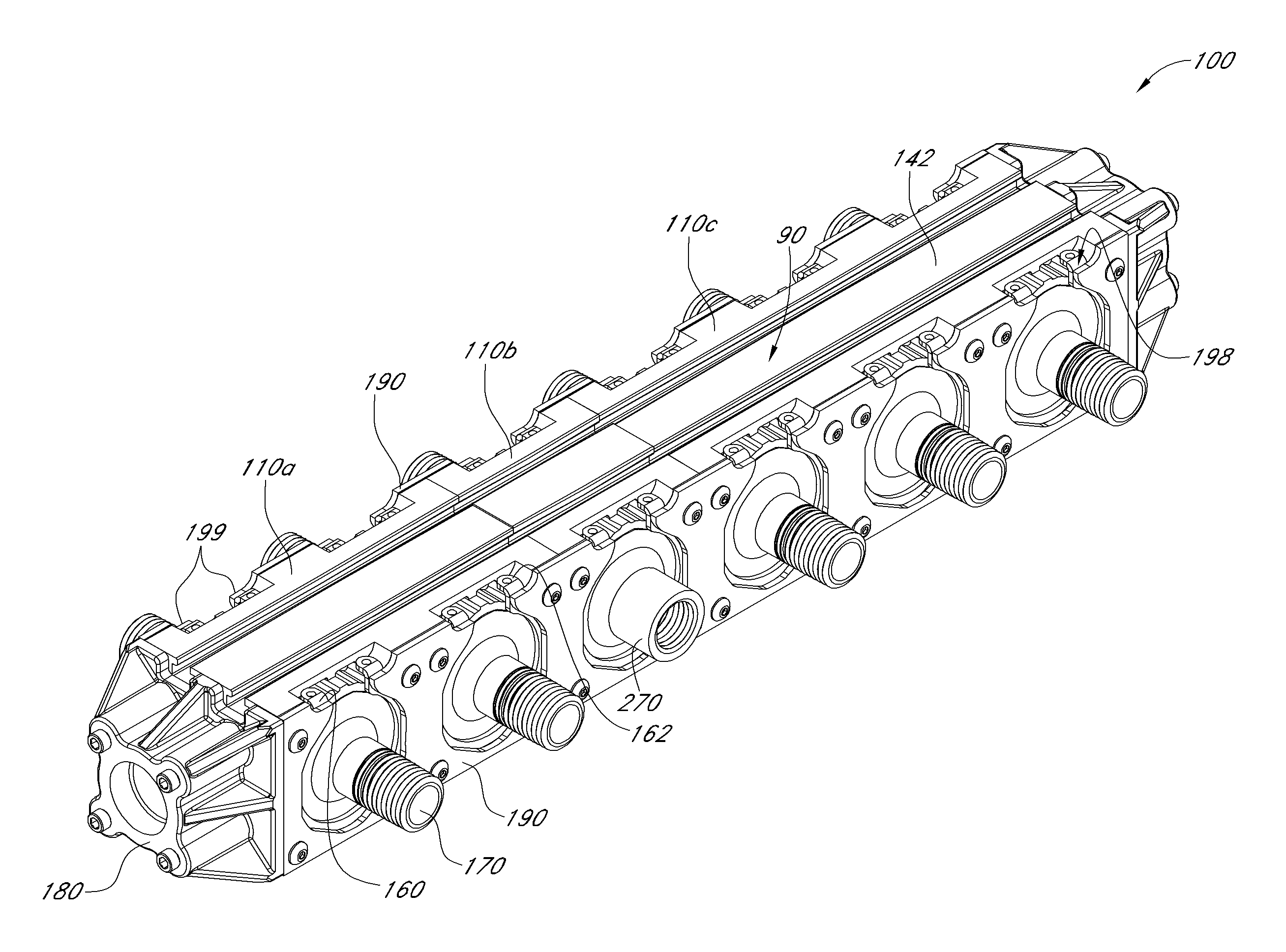
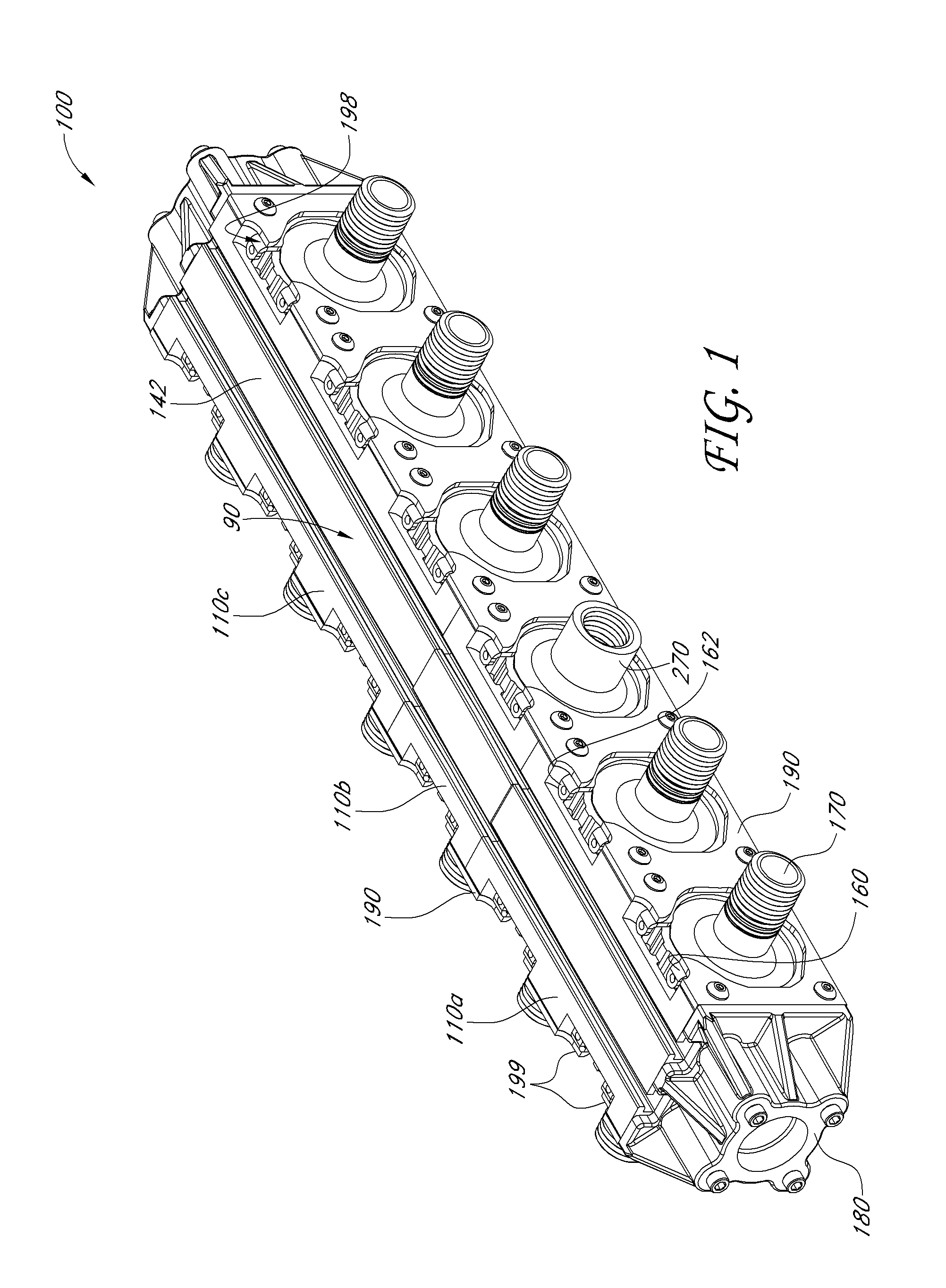
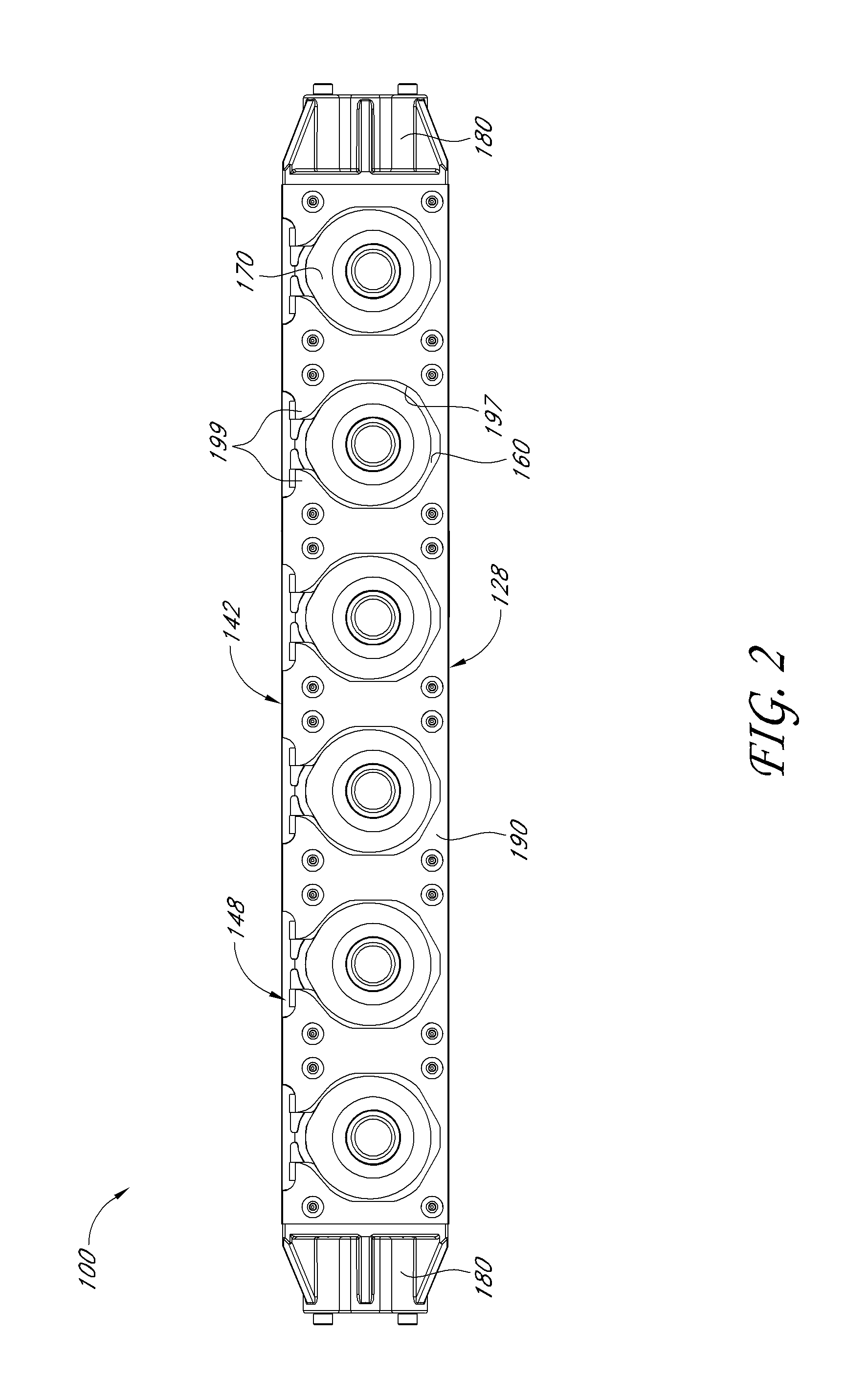
[0085]With initial reference to FIGS. 1-5, an embodiment of a manifold 100 is shown, which manifold 100 can be used in conjunction with valves and valve control systems for a fluid flow system. The illustrated manifold 100 is presented herein as an example to aid in describing principles and structure in accordance with several embodiments. It is understood that manifolds having a different appearance or differences in specific structure may still employ one or more of the principles discussed herein.

[0086]The illustrated manifold 100 comprises a modular manifold system that allows the size of the manifold 100 to be adjusted and configured to meet the needs of the particular application. In this embodiment the manifold 100 comprises a manifold body assembly 90 made up of three modules 110a-c. Preferably multiple modules 110 are connected end to end, and a cladding or plate 190 spans a length of the body 90 across the modules. A more detailed discussion of the modules is presented be...


PUM


Abstract

A manifold for accommodating at least one fluid is constructed of a plurality of modules that can be interconnected and configured to create a customized manifold. Couplers interconnecting a flow cavity of each module can be selected to determine fluid flow characteristics between module flow cavities. Each module has one or more valve ports. Valves or other flow accommodating apparatus are attached to the manifold via adapters. A first end of each adapter is sized and configured to engage a valve port, and a second end engages the attached apparatus.

Description

BACKGROUND[0001]1. Field of the Invention[0002]This invention relates to fluid control devices and in particular this invention relates to a modular manifold and valve assembly.[0003]2. Description of the Related Art[0004]Manifolds are often used to direct fluid from a supply source to several outlets. Each installation may include a variety of valve inlets and outlets customized for the specific application. Customization of manifold and valve systems can be costly and require extensive time and specialized equipment specific to the valve system. Additionally, modifying an existing system such as to increase or decrease valve capacity and / or to change fluid flow paths may require acquiring an entirely new manifold or performing extensive modifications that are impractical in the field of service.[0005]Additionally, valves generally are screwed directly on to the manifold, thus requiring the manifold to be large enough to accommodate the rotation of the valve body. In applications w...

Claims


Application Information

Patent Timeline
IPC IPC(8): F16L41/00
CPCF16L41/03F16L39/06F16K27/003Y10T137/85938Y10T137/5283
Inventor ELLIS, MICHAEL ROBERT
Owner COAST PNEUMATICS
Learn More