Vehicle for line marking

a line marking and vehicle technology, applied in the field of vehicles, can solve the problems of too fast steering and too slow steering, and achieve the effects of reducing the speed at which the wheel rotates, restricting the steering angle, and speeding up the steering

Active Publication Date: 2015-10-01
WATSON DIANE LEE
View PDF14 Cites 11 Cited by
  • Summary
  • Abstract
  • Description
  • Claims
  • Application Information

AI Technical Summary

Benefits of technology

[0013]This is addressed by a variable ratio steering system which enables the directional wheel to be able to rotate as much as 200° (ie 100° either side of straight line alignment) with the rate at which the wheel rotates reducing the further the wheel is rotated away from the straight line alignment.
[0014]The applicants have achieved this by using a single universal joint between a primary steering mechanism and the secondary steering mechanism. By inclining the actuator wheel of the primary steering mechanism steering wheel at an angle to the steering actuator of the secondary steering mechanism back towards the operator, the natural operation of the universal joint to alter the speed at which two shafts turn relative to each other as the universal joint rotates can be utilised to give the effect of producing a small rotation of the directional wheel when a rotation is applied to the steering wheel effectively producing a slow rotation when the directional wheel is substantially pointed straight ahead, and producing a larger rotation when the same corresponding rotation is applied when the directional wheel is rotated out of away from the straight ahead alignment. This has the effect of speeding the steering up when turning sharply either left of right without restricting steering angle.

Problems solved by technology

The applicants found that if a direct ratio steering system was used to control the directional wheel, then in the modes of operation, namely straight line marking or small radius cornering, direct ratio steering created a problem in that the steering was too fast when driving in a straight line and at the same time too slow when turning sharply.

Method used


Image

  • Vehicle for line marking
  • Vehicle for line marking
  • Vehicle for line marking

Examples


Embodiment Construction

[0033]It will be understood that the invention disclosed and defined in this specification extends to all alternative combinations of two or more of the individual features mentioned or evident from the text or drawings. All of these different combinations constitute various alternative aspects of the invention.

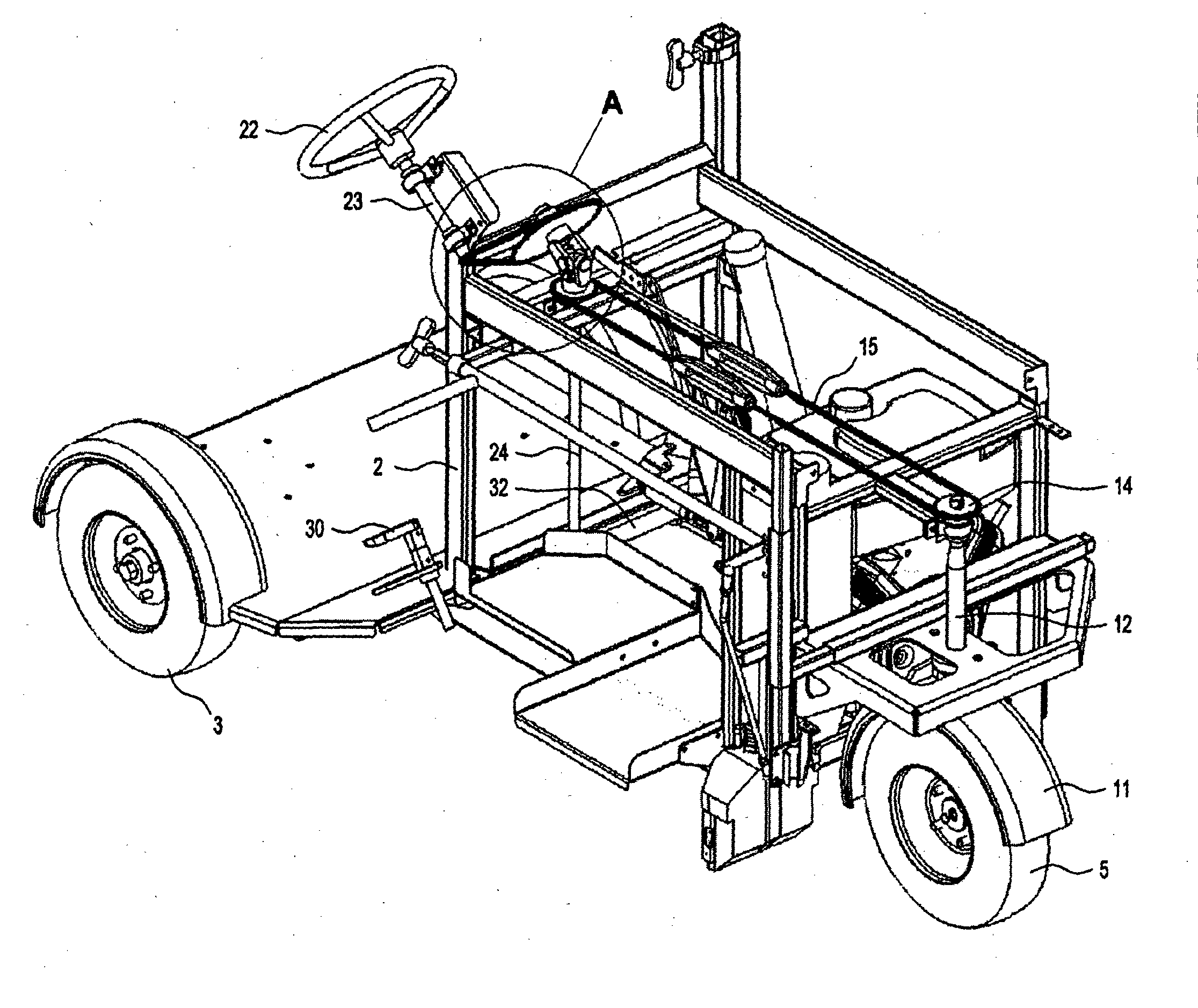
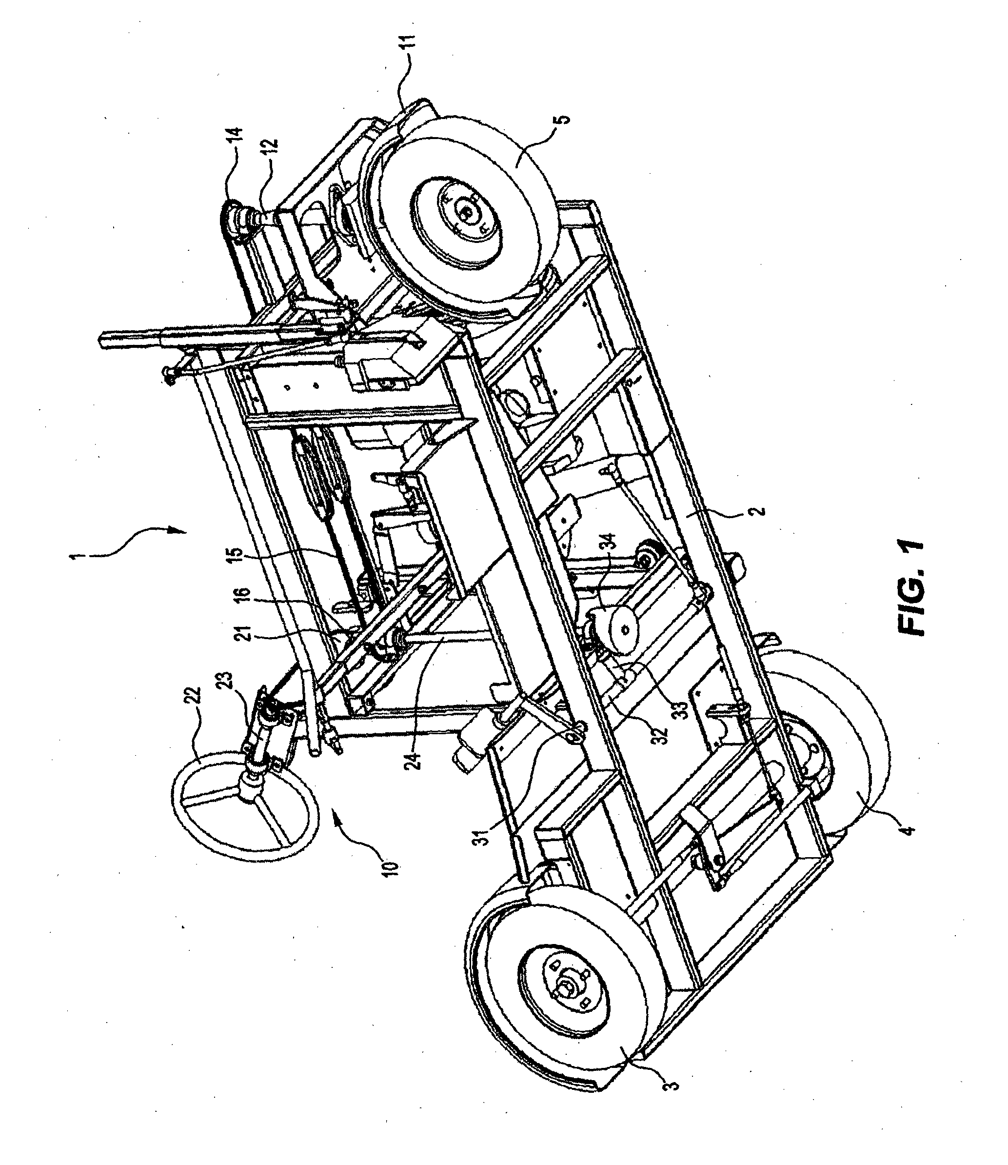
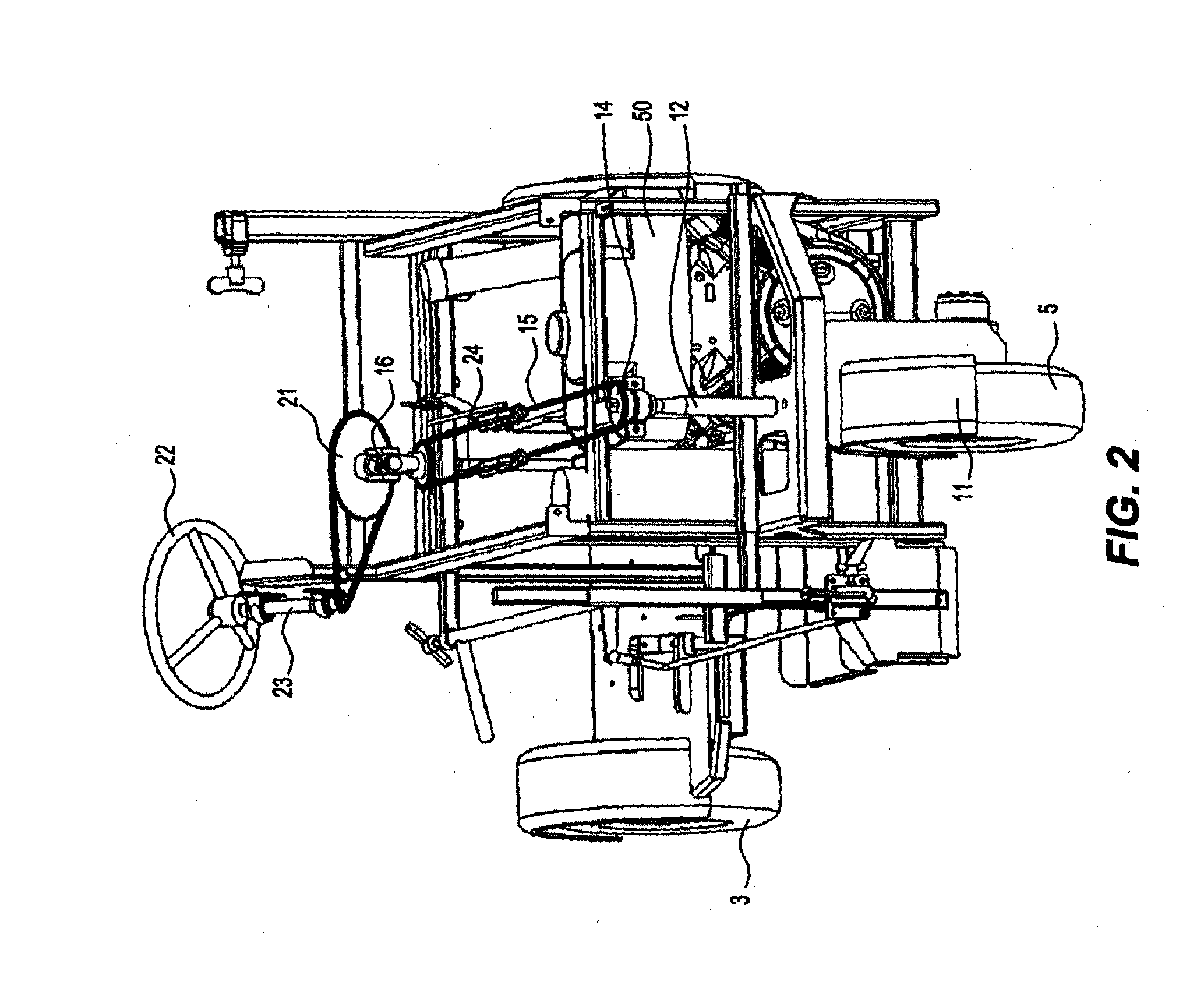
[0034]Referring to the drawings, the apparatus 1 according to one embodiment includes a frame 2, and wheels 3, 4, 5 supporting the frame 2. At least one of the wheels 5 is a directional wheel which determines the direction of movement of the apparatus 1. The apparatus includes a steering mechanism 10 including a primary and secondary steering mechanism. The primary steering mechanism including a mounting 11 for the directional wheel 5, the mounting 11 including a steering shaft 12 having an axis about which the directional wheel 5 rotates to direct the direction of movement of the apparatus. The steering shaft 12 is coupled through a shaft actuator to a steering actuator both...


PUM


Abstract

A vehicle for line marking, having a steering mechanism (10) including: a directional wheel (5) that pivots about a steering shaft (12) coupled to a steering actuator (13); a control actuator (21) responsive to a steering wheel (22); and a universal joint coupling the control actuator (21) and the steering actuator (13) at a fixed angle between 20° to 70°, preferably 30° to 60°; the angle of the universal joint acting to produce a varying steering ratio as the steering wheel is moved away from its centred position. The vehicle includes a hydraulic pump circuit for a motor (101) driven line marking spray device (77) having a hydraulic supply line (105) for the motor with a check valve (107) and a high pressure accumulator (109) between the check valve and the motor and a pressure actuated ram (102) to deactivate the pump (100) when the pressure exceeds a threshold; the motor return line having a low pressure accumulator (110) and a restricted (112) bypass line (111).

Description

FIELD OF THE INVENTION[0001]This invention relates to vehicle particularly suitable as an apparatus for applying markings to surfaces such as roads, sports playing surfaces, car parks and other areas where permanent or temporary markings are desired. These types of apparatus are herein referred to as line marking apparatus.BACKGROUND OF THE INVENTION[0002]In order to meet a market for line marking apparatus, three different types of apparatus have been developed. Two of these types of line marking apparatus are large self-propelled machines that are used for big areas and the fast marking of roads. The largest of these are based on conventional trucks that are modified to carry over a thousand litres of paint and cover large distances. These apparatus are useful for roads with wide radius bends and are able to mark such roads quickly without reloading or stopping.[0003]The second type are a little smaller and more manoeuvrable. It generally weighs over a tonne and is suitable for ar...

Claims


Application Information

Patent Timeline
Patent Type & Authority Applications(United States)
IPC IPC(8): E01C23/22A63C19/06B60K26/02B05B13/00B62D3/02B62D1/20
CPCE01C23/22B62D3/02B62D1/20A63C2019/067B05B13/005A63C19/065B60K26/02B62D1/16F04B11/0008F15B2211/20553F15B2211/20576F15B2211/613F15B2211/625F15B2211/7058
Inventor LUCAS, REX CAMERONWATSON, CARL WILLIAM
Owner WATSON DIANE LEE
Why Eureka
Try Eureka