Wheel assembly for moving caliper jaw with repeatable force

a caliper and jaw technology, applied in the field of precision measurement instruments, can solve the problems of unreliable or non-repeatable measurement of objects, the variation of force which can be applied by the measuring jaw and the differences in measurement which can occur, and the inability to use prior calipers, so as to prevent plastic deformation

Active Publication Date: 2015-09-03
MITUTOYO CORP
View PDF8 Cites 11 Cited by
  • Summary
  • Abstract
  • Description
  • Claims
  • Application Information

AI Technical Summary

Benefits of technology

[0013]The displacement indicator may include a pointer element coupled to the rotary bearing member and extending through a clearance opening in the rotary actuation member. In one implementation, the pointer element may be rigidly coupled to the rotary bearing member. In addition, the clearance opening may be sized such that a maximum amount of travel of the pointer element in the clearance opening may provide a maximum rotational displacement limit between the rotary bearing member and the rotary actuation member. Such a limit may substantially prevent plastic deformation of the compliant coupling element.

Problems solved by technology

As described in the '009 publication, one deficiency in the use of prior calipers is the variation in force which can be applied by the measuring jaws and the differences in measurement which can occur as a result.
Particularly when a soft object is being measured, the measurement of the object may be unreliable or non-repeatable because one may apply either a higher force on the jaws of the caliper such that the soft object is “more compressed”, or apply a lower force such that the soft object is “less compressed”.
However, the force sensing and indicating features of the caliper of the '009 publication may be considered “overkill” in many applications, and / or may be considered too expensive and / or complex by many caliper users.

Method used


Image

  • Wheel assembly for moving caliper jaw with repeatable force
  • Wheel assembly for moving caliper jaw with repeatable force
  • Wheel assembly for moving caliper jaw with repeatable force

Examples


first embodiment

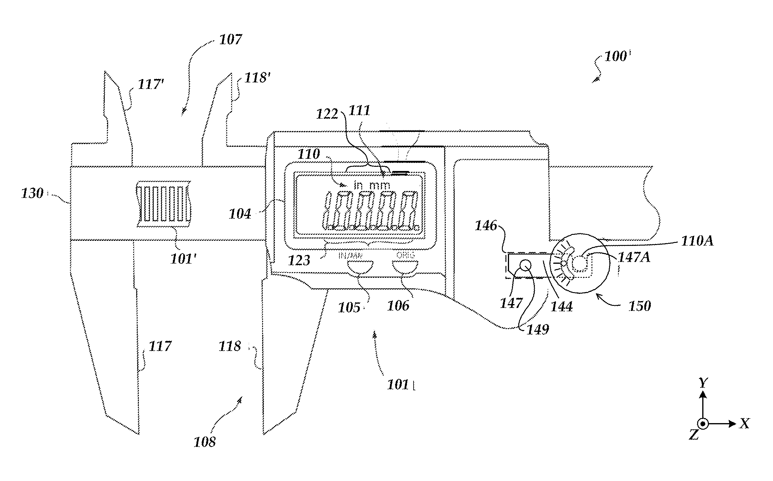
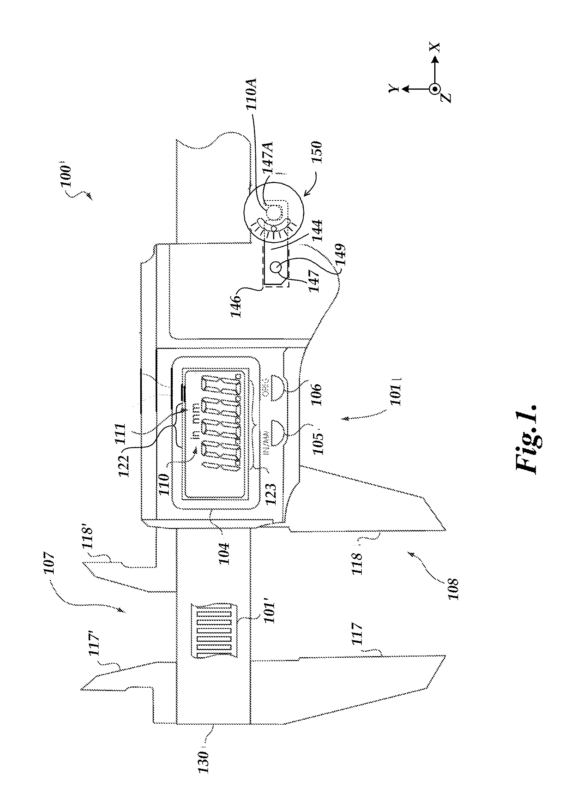
[0022]FIG. 1 shows a portion of a caliper 100 with a wheel assembly 150. The caliper 100 includes a scale member 107 and a read-head member 108. The scale member 107 may be a conventional electronic caliper member comprising fixed jaw portions 117 and 117′ and a spar 130 carrying a transducer scale 101′, a portion of which is revealed in FIG. 1. The read-head member 108 may be a conventional electronic caliper member including jaw portions 118 and 118′, a hub capture element 144 for coupling to the wheel assembly 150, and a guide and mounting portion (not shown) that aligns and guides the read-head member 108 along the spar 130 and carries a read-head assembly 101. The guide and mounting portion (as known by one of ordinary skill in the art and / or as disclosed in the incorporated references) underlies the read-head assembly 101 shown in FIG. 1, and is approximately the same size as the read-head assembly 101.

[0023]In the embodiment shown in FIG. 1, the read-head member 108 carries t...

second embodiment

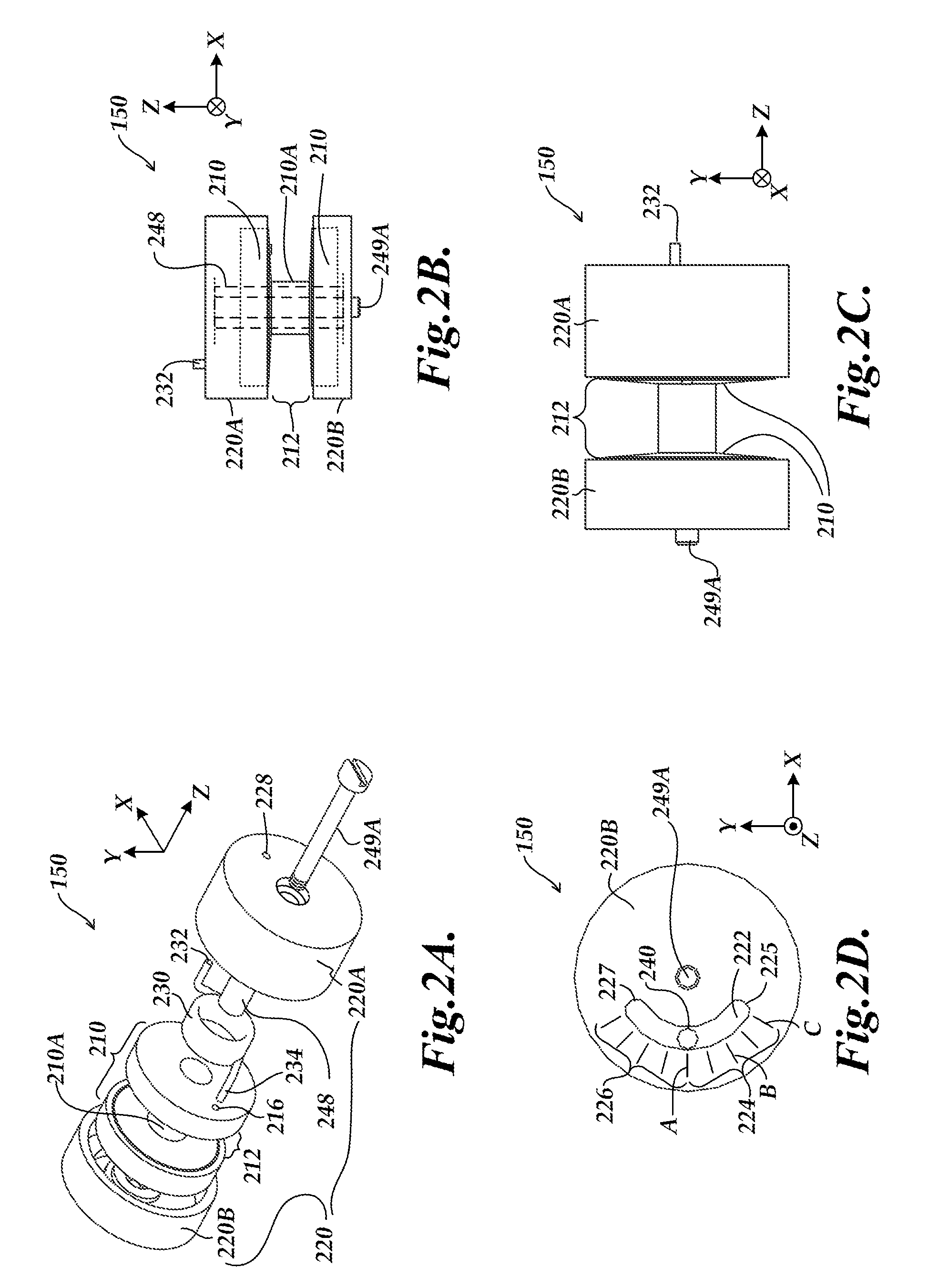
[0046]FIGS. 5A-5D are diagrams of a wheel assembly 550 in which a displacement indicator is not included. It will be appreciated that the components of the wheel assembly 550 may be similar or identical to the similarly numbered components of the wheel assembly 150 of FIGS. 2A-2D, and will be understood to operate in the same manner except as otherwise described below. As shown in FIGS. 5A-5D, the wheel assembly 550 includes a rotary bearing member 210, a rotary actuation member 220, and a compliant coupling element 230.

[0047]The primary difference of the wheel assembly 550 as compared to the wheel assembly 150 is the lack of a displacement indicator. As shown in FIG. 5D (as compared to FIG. 2D), the outer surface of the rotary actuator portion 220B does not include a clearance opening or a visual displacement indicator. Instead, only the amount of rotation of the rotary actuation member 220 and the manually sensed (tactile) resistance provided by the compliant coupling element 230 ...

third embodiment

[0050]FIG. 6 is a diagram of a wheel assembly 550′ in which an auditory and / or tactile displacement indicator provides auditory and / or tactile feedback (e.g., a clicking) related to a changing or target amount of applied measuring force in a caliper. It will be appreciated that the components of the wheel assembly 550′ may be similar or identical to the similarly numbered components of the wheel assembly 550 of FIGS. 5A-5D, and will be understood to operate in the same manner except as otherwise described below. As shown in FIG. 6, the rotary bearing member 210′ includes a schematically represented noise generating feature 21ONGF (e.g., ridges, knurling, holes, bumps, etc.) and the rotary actuation member 220 includes a schematically represented cooperating noise generating feature 22ONGF (e.g., a spring member including a raised portion that clicks over elements of the noise generating feature 21ONGF during relative motion).

[0051]In operation, a user may determine that a proper amo...


PUM


Abstract

A compliant wheel assembly is provided for moving a caliper jaw relative to a caliper spar. The wheel assembly includes a rotary bearing member, a rotary actuation member and a compliant coupling element. The rotary bearing member is coupled to the caliper jaw and may engage the caliper spar. The rotary actuation member is actuated by a user to apply a measuring force. The compliant coupling element is configured to compliantly couple the rotary actuation member to the rotary bearing member. Using the compliant wheel assembly, a user is able to apply a more consistent amount of measurement force than could typically be achieved with a conventional rigid thumb wheel in caliper. In one implementation, a displacement indicator may also be provided that is responsive to the rotational displacement between the rotary bearing and actuation members for indicating an amount of measurement force that is being applied.

Description

BACKGROUND[0001]1. Technical Field[0002]The invention relates to precision measurement instruments, and particularly to calipers with a movable jaw for measuring the dimensions of an object.[0003]2. Description Related Art[0004]Calipers are known that utilize pairs of jaws for determining measurements. A first jaw is generally fixed at one end of a measurement scale while a second jaw is attached to a slider assembly that moves along the measurement scale. An outer dimension of an object may be measured by arranging the object between and against inner surfaces of the first and second jaws. An inner dimension of an object may be measured by arranging outer surfaces of the first and second jaws between and against the inner surfaces of the object (e.g., the walls of a hole). The slider assembly may be moved with a user's thumb, and a thumb wheel may be provided for enabling controlled movement of the slider. One exemplary caliper utilizing a thumb wheel is described in U.S. Pat. No. ...

Claims


Application Information

Patent Timeline
Patent Type & Authority Applications(United States)
IPC IPC(8): G01B3/20
CPCG01B3/205Y10T74/18568
Inventor EMTMAN, CASEY E.GOLDSWORTHY, MICHAEL EDWARDGARRITY, WILLIAM RANDALL
Owner MITUTOYO CORP
Why Eureka
Try Eureka