Wire feed motor control systems and methods

a control system and wire feed technology, applied in the field of wire feed drive system, can solve the problems of affecting the wire feed rate, the speed of the motor may change, and the unsatisfactory variation of the wire feed ra

Inactive Publication Date: 2011-09-15
ILLINOIS TOOL WORKS INC
View PDF20 Cites 27 Cited by
  • Summary
  • Abstract
  • Description
  • Claims
  • Application Information

AI Technical Summary

Problems solved by technology

However, the speed of each of the motors may vary during the wire feeding operation, often leading to undesirable variations in the wire feed rate.
For example, during operation, as each of the motors generates operational heat, the speed of the motors may change (e.g., increase), thus affecting the wire feed rate, and possibly placing the welding wire under undesired stress.
Such features limit the efficiency and utility of traditional wire feeders.

Method used


Image

  • Wire feed motor control systems and methods
  • Wire feed motor control systems and methods
  • Wire feed motor control systems and methods

Examples


Embodiment Construction

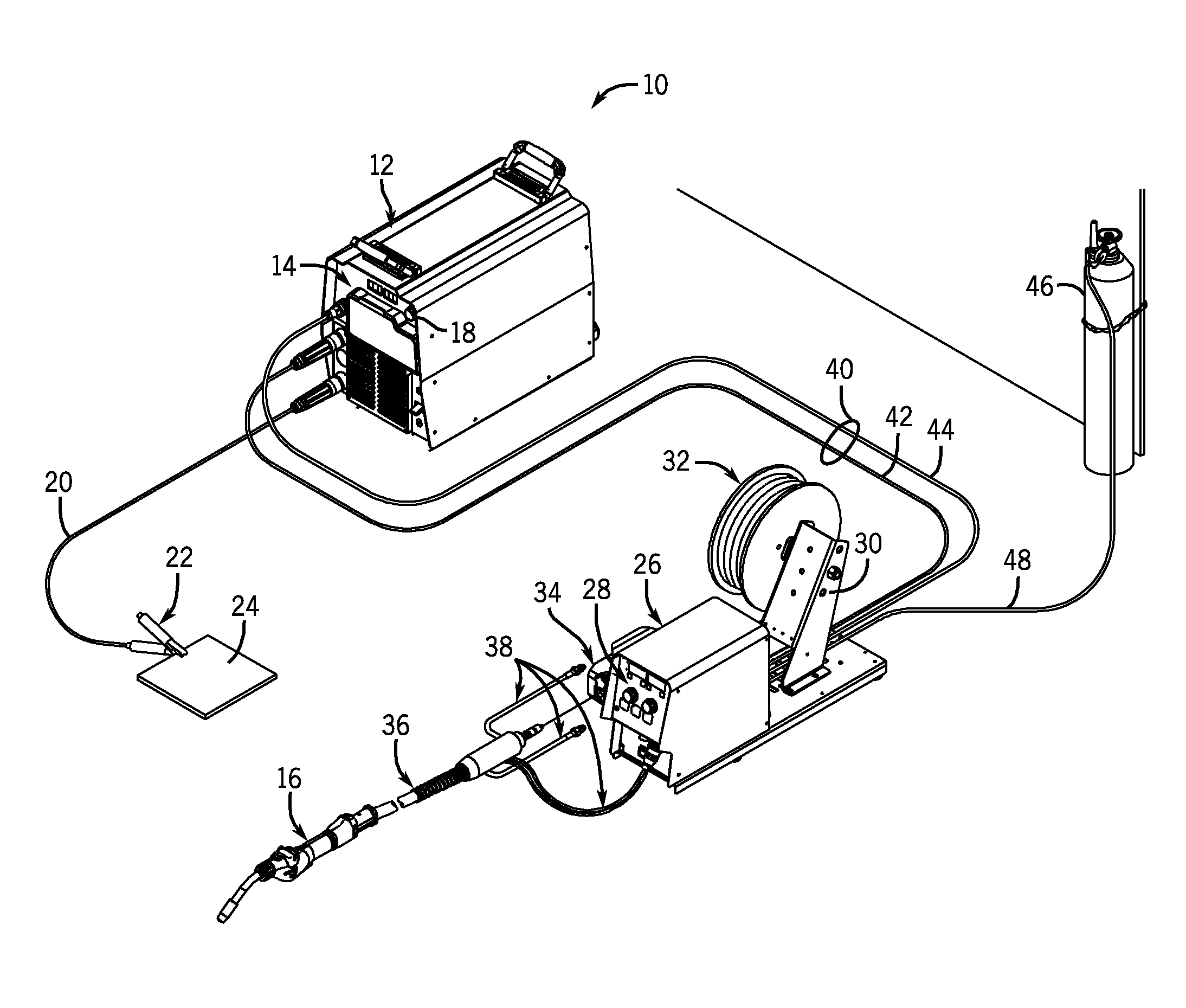
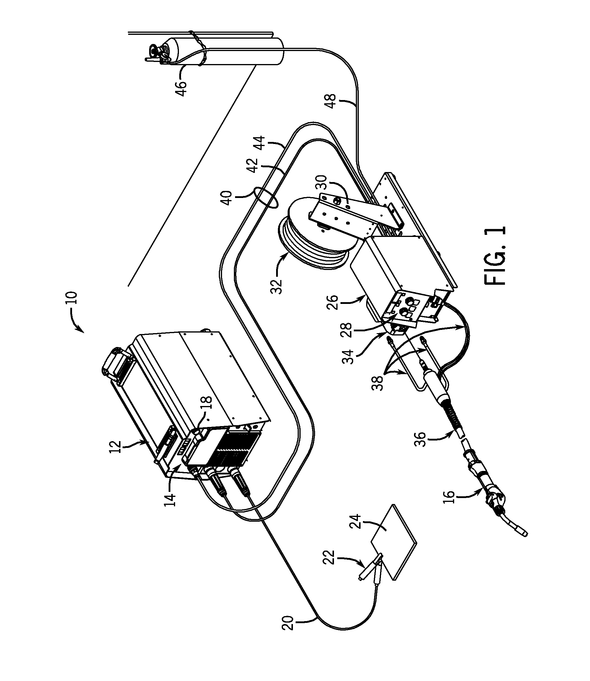
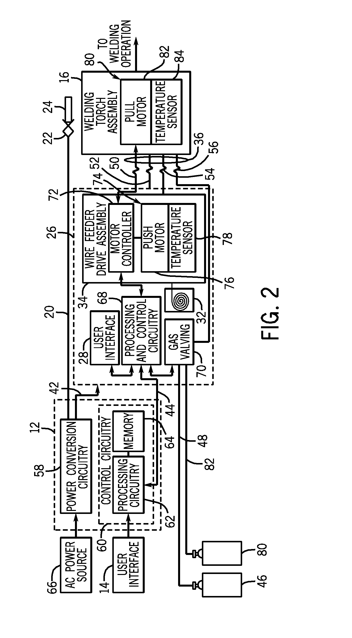
[0014]As described in detail below, embodiments are described of a welding system including a speed control system configured to control a substantially uniform push-pull welding wire feed from a wire spool to a welding operation via a welding torch. Embodiments of the welding systems disclosed herein may include one or more temperature sensors associated with at least one of the push motor and the pull motor of the wire drive assemblies configured to feed the welding wire through the welding torch to the welding operation. A controller of the speed control system disposed, for example, in the welding wire feeder, receives feedback from the one or more temperature sensors and, based on such feedback, determines one or more temperature dependent constants. As such, the controller may utilize motor temperature feedback to adjust one or more parameters (e.g., a motor armature resistance value) of the wire feed operation to maintain the velocity of the push motor and / or the pull motor a...


PUM

PropertyMeasurementUnit
temperatureaaaaaaaaaa
speedaaaaaaaaaa
resistance valueaaaaaaaaaa

Abstract

Wire feed drive assemblies having welding wire mounted thereon and a motor that rotates a wire feed roller to drive the weld wire toward a welding torch are provided. The wire feed drive assemblies also include a temperature sensor coupled to the motor and adapted to measure a temperature of the motor. The wire feed drive assemblies further include a motor controller coupled to the temperature sensor and the motor and adapted to receive temperature feedback from the temperature sensor and to utilize the temperature feedback to regulate a speed of the motor.

Description

CROSS REFERENCE TO RELATED APPLICATIONS[0001]This application is a Non-Provisional Patent Application of U.S. Provisional Patent Application No. 61 / 312,531, entitled “Motor Temperature Estimator”, filed Mar. 10, 2010, which is herein incorporated by reference.BACKGROUND[0002]The invention relates generally to welding systems, and, more particularly, to a wire feed drive system for use in a welding system.[0003]Welding is a process that has become increasingly ubiquitous in various industries and applications. While such processes may be automated in certain contexts, a large number of applications continue to exist for manual welding operations. Such welding operations rely on a variety of types of equipment to ensure the supply of welding consumables (e.g., wire feed, shielding gas, etc.) is provided to the weld in an appropriate amount at the desired time. For example, metal inert gas (MIG) welding typically relies on a wire feeder to ensure a proper wire feed reaches a welding to...

Claims


Application Information

Patent Timeline
Patent Type & Authority Applications(United States)
IPC IPC(8): B23K9/10B23K9/26
CPCB23K9/124
Inventor MEHN, PETER DONALD
Owner ILLINOIS TOOL WORKS INC
Why Eureka
Try Eureka