Protective barrier for winds carrying snow or sand

Inactive Publication Date: 2011-09-15
CASTRO FRESNO DANIEL +5
View PDF4 Cites 9 Cited by
  • Summary
  • Abstract
  • Description
  • Claims
  • Application Information

AI Technical Summary

Benefits of technology

[0037]In FIG. 1, we do not full see the fastening plates in the ends of the barrier, but rather only up to the ring (6) which is anchored into the vertical post. This is because these end fastening

Problems solved by technology

The disadvantage of this system is that the vegetation is useful whe

Method used


Image

  • Protective barrier for winds carrying snow or sand
  • Protective barrier for winds carrying snow or sand
  • Protective barrier for winds carrying snow or sand

Examples


Embodiment Construction

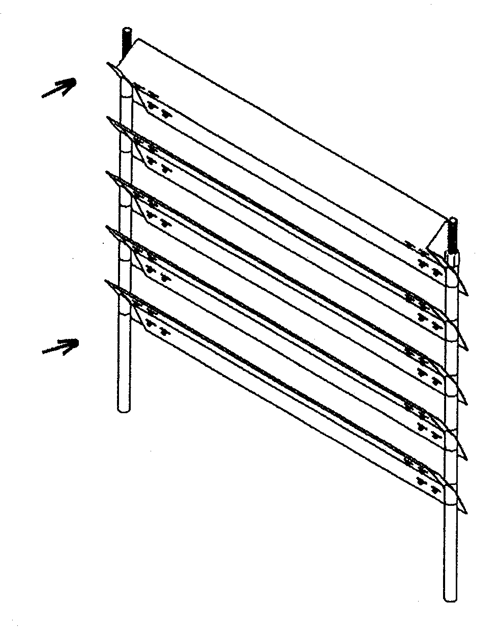
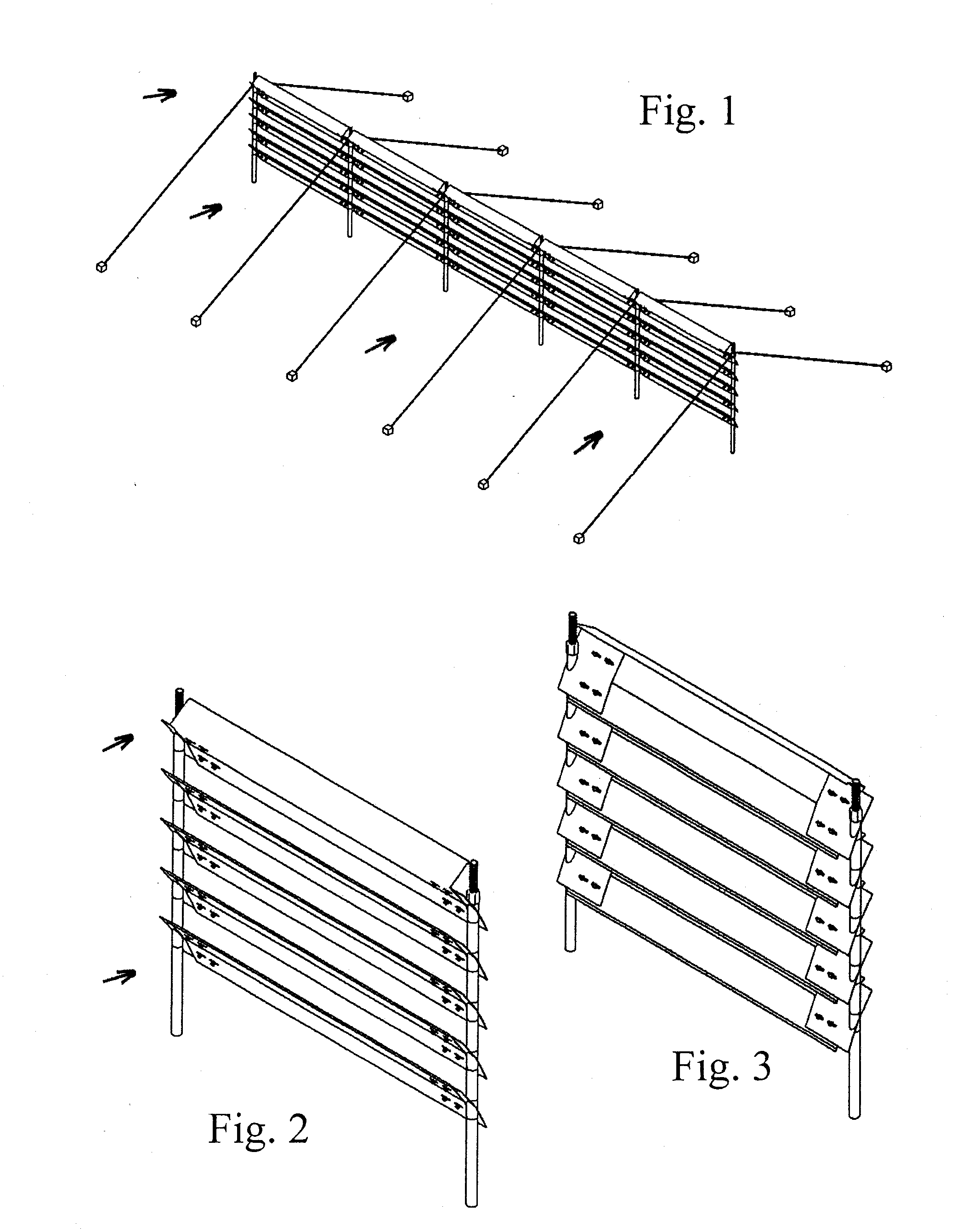
[0006]The proposed invention consists of a protective barrier against winds carrying snow or sand composed of a set of easily transportable parts to the site in order to form a barrier by arranging a number of screens in a line. The structure of the invention's elements facilitates a quick and simple on-site installation and replacement of worn parts during repair and maintenance work.

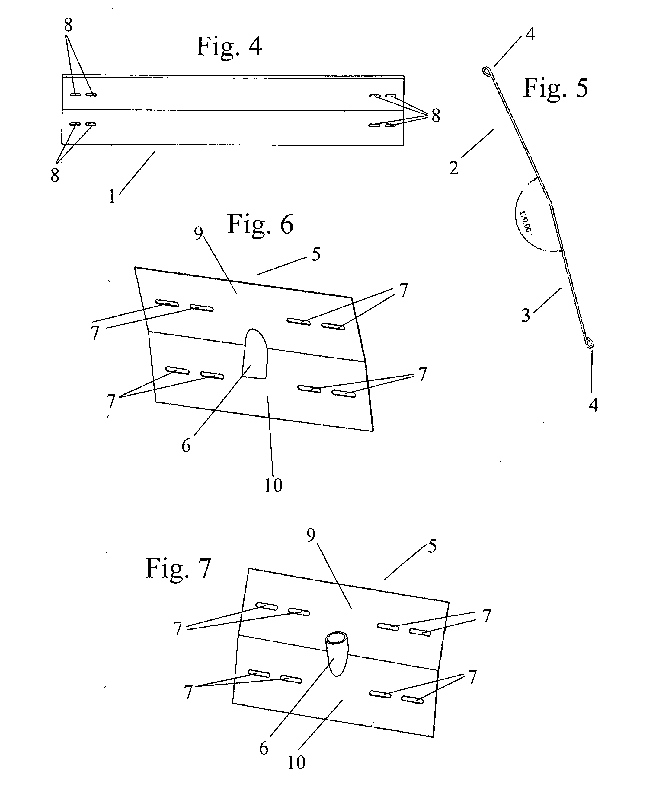
[0007]Each screen consists of a group of strips to be positioned horizontally, superimposed at regular distances, bound to the vertical posts by fastening their ends to rectangular fastening plates that are inserted into the vertical post using a tubular ring found in the plate's structure.

[0008]The line of screens that forms the barrier will force the wind to pass through its structure, dissipating its velocity and avoiding eddies in the protected zone, eddies that cause accidents since they impede the drivers' view of the roadway.

[0009]The screen will have a wind deflector in its upper part that will...


PUM


Abstract

Protective barrier for snowstorms, for installation near communication routes in order to prevent the accumulation of snow or sand on the road. The barrier is formed by joining several screens made of a set of blades that are arranged horizontally, superposed on one another at regular distances, joined with vertical posts by anchoring their ends to several rectangular plates that are inserted in the vertical post using a ring on the plate.

Description

FIELD OF INVENTION[0001]As stated in the declaration of this descriptive report, the present invention refers to a barrier intended to protect transportation routes, such as train tracks, roads and highways from accumulations of snow or sand carried by winds, by preventing the wind from directly lashing the route, thereby depositing and accumulating the storm's materials outside the transportation route.BACKGROUND OF THE INVENTION[0002]Different methods are known for protecting routes from winds carrying snow or sand. The most traditional methods are wooden barriers with panels arranged horizontally equidistant from each other, attached to vertical posts to form a barrier.[0003]Other barriers incorporate metallic posts positioned vertically into the ground together with plastic or synthetic materials as its horizontal elements. There are also mixed barriers built with wooden boards and steel posts. U.S. Design Pat. No. D353.206 claims for the ornamental design of a fibreglass snow f...

Claims


Application Information

Patent Timeline
IPC IPC(8): E01F7/02
CPCE01F7/02E01F7/025
Inventor CASTRO FRESNO, DANIELRODRIGUEZ HERNANDEZ, JORGESANUDO FONTANEDA, LUIS ANGELDEL COZ DIAZ, JUAN JOSEALVAREZ RABANAL, FELIPE PEDROGARCIA NIETO, PAULINO JOSE
Owner CASTRO FRESNO DANIEL
Why Eureka
Try Eureka