Communication system and receiver

a communication system and receiver technology, applied in the field of communication systems, can solve the problems of spoiled aesthetic appearance, limited users who can enjoy private images, and system that requires use of light shutters that are less convenien

Active Publication Date: 2011-09-15
NEC CORP
View PDF7 Cites 53 Cited by
  • Summary
  • Abstract
  • Description
  • Claims
  • Application Information

AI Technical Summary

Benefits of technology

It is therefore an object of the present invention to provide a communication system that can perform visible light communication by use of a simple means without spoiling any aesthetic appearance of the public image displayed on the display apparatus, and a receiver for use in the communication system.

Problems solved by technology

In the visible light communication technologies described above, there is the problem that if, for example, a two-dimensional code is displayed on a large-scale display used on the street, the two-dimensional code will occupy part of the image (public image) such as an advertisement etc. displayed for the public, the aesthetic appearance will be spoiled.
Accordingly, users who can enjoy the private image are limited.
For example, when an advertisement etc. is displayed as the public image while the URL (Uniform Resource Locator) of the server equipment that provides the detail information on the product displayed by the public image is displayed by a two-dimensional code or the like, a system that requires use of the light shutter is less convenient.
However, in visual light communications, it is not always possible for the user to receive the synchronization signal because in such a case various kinds of information are acquired from the image displayed on a large-scale display that is located far away, for example.
However, since the system that needs a special device to acquire the private image as described is not desirable, it is preferred that even a device that has a relatively low image processing capability as, for example a built-in camera of a mobile phone, acquire the private image.

Method used


Image

  • Communication system and receiver
  • Communication system and receiver
  • Communication system and receiver

Examples


first exemplary embodiment

The First Exemplary Embodiment

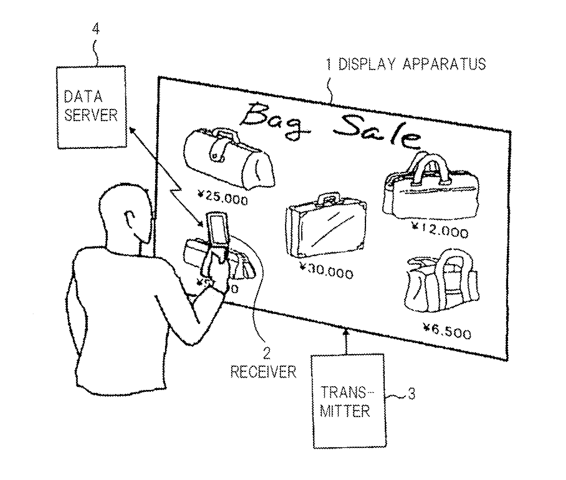
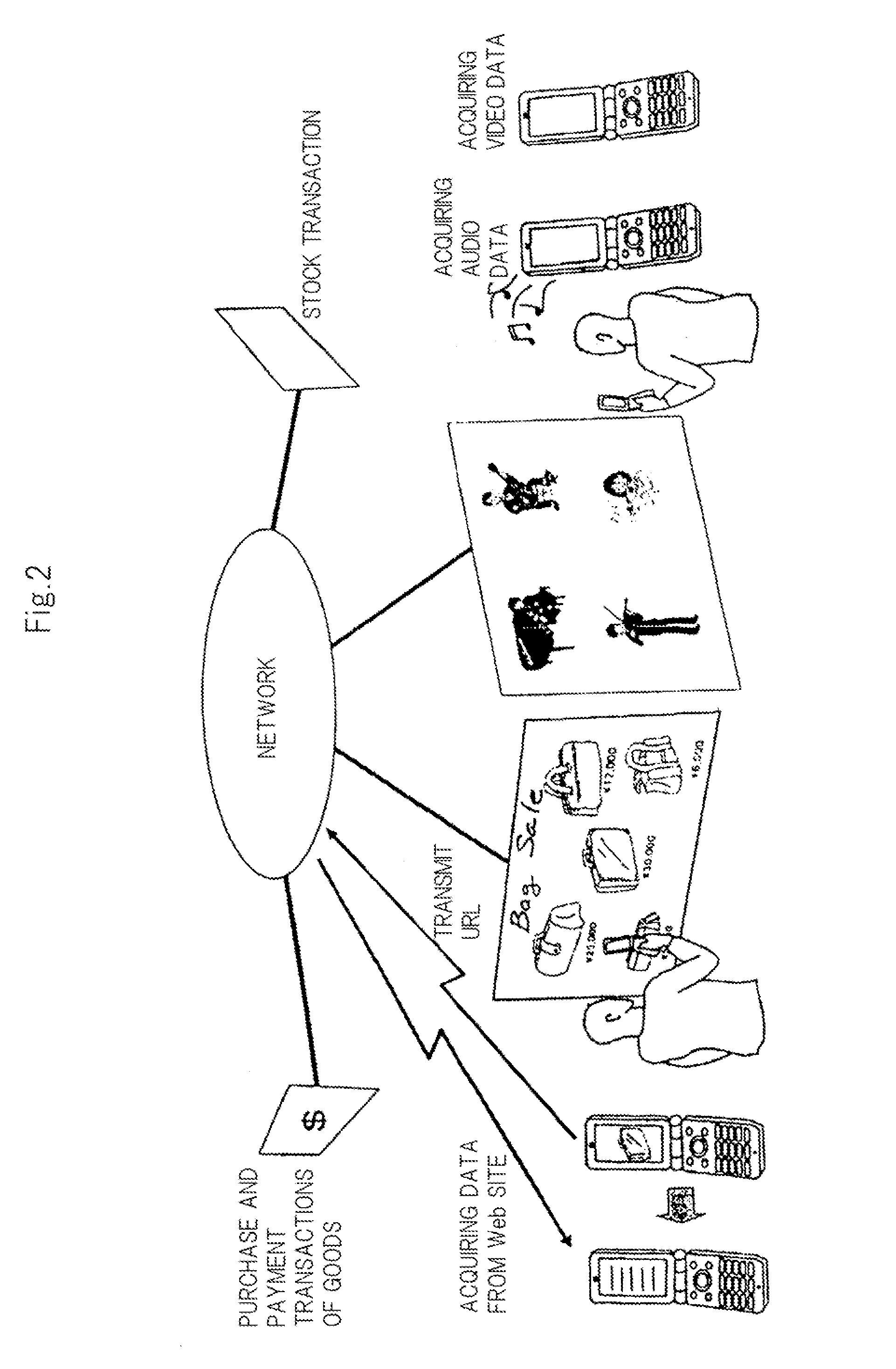
FIG. 1 is a schematic diagram showing one configurational example of a communication system of the first exemplary embodiment. FIG. 2 is a schematic diagram showing one configurational example of a network system using the communication system shown in FIG. 1.

As shown in FIG. 1, the communication system of the first exemplary embodiment includes: display apparatus 1 displaying a public image, a private image and its reversal image; transmitter 3 outputting image signals for displaying each image on display apparatus 1; receiver 2 owned by a user for acquiring the public image or the private image from the image displayed on display apparatus 1; and data server 4 transmitting data of various kinds of content to receiver 2 by means of a well-known communication means.

Transmitter 3 can be realized by an A / D converter for processing image signals, CPU, DSP, logical operation circuit or the like implementing processing in accordance with programs. Display ap...

second exemplary embodiment

The Second Exemplary Embodiment

Next, the second exemplary embodiment of the present invention will be described with reference to the drawings.

In the above-described communication system of the first exemplary embodiment, the public image is acquired by receiver 2 when the user moves ¼ wave plate 26 and polarizing plate 27 to a position where the light receiver of the camera is not covered, whereas the private image is acquired by receiver 2 when the user moves ¼ wave plate 26 and polarizing plate 27 to a position where the light receiver of camera 21 is covered. Accordingly, in receiver 2 of the first exemplary embodiment, when receiver 2 is made to display the public image, it is relatively difficult to switch the display to the private image while keeping its posture.

The second exemplary embodiment proposes receiver 2 that can switch the display between the public image and the private image in a simpler manner. Display apparatus 1, transmitter 3 and data server 4 included in the...

third exemplary embodiment

The Third Exemplary Embodiment

Next, the third exemplary embodiment of the present invention will be described with reference to the drawings.

In the above second exemplary embodiment, when liquid crystal 40 included in receiver 2 is off, the private image is displayed on terminal display unit 24, whereas when the liquid crystal cell 40 is on, the user views the public image displayed on terminal display unit 24.

It is generally considered that when a user uses receiver 2, there are more chances to display the public image than to display the private image. Therefore, the power consumption of receiver 2 is prone to increase because in receiver 2 of the second exemplary embodiment, voltage needs to be applied to liquid crystal cell 40 when the public image that is displayed frequently is displayed. Because receiver 2 is realized by a portable type terminal device such as a mobile phone as described above, any increase in power consumption brings on exhaustion of the battery in the termi...


PUM


Abstract

A transmitter that outputs an image signal for displaying a first image and outputs an image signal of a synthesized image made of the reversal image of the first image and a second image. A display apparatus, based on the image signals output from the transmitter, displays the first image and the synthesized image with circular polarizations having different senses of rotation from each other. A receiver includes a circular polarization selecting and transmitting means that separates the first image and the synthesized image displayed on the display apparatus, based on the sense of rotation of the circular polarization, and selectively allows the images to pass therethrough, so as to be able to photograph the first image displayed on the display apparatus.

Description

TECHNICAL FIELDThe present invention relates to a communication system for conveying information by means of an image or movie displayed on a display or the like and a receiver used in the communication system.BACKGROUND ARTAs a visible light communication technology for conveying information by means of an image or movie displayed on a display or the like, there has been a known system in which a special two-dimensional code (QR code) or the like is displayed on part of a displayed image so that the camera of a mobile phone etc., photographs the two-dimensional code to receive information.For example, Patent Document 1 discloses a configuration which, when an anomaly is detected in a vehicle navigation system, enables visual check of fault diagnosis data by generating fault diagnosis data including an anomalous signal that indicates the anomaly, by converting the fault diagnosis data into a symbol code (bar code or two-dimensional code) to be displayed on a display apparatus, and b...

Claims


Application Information

Patent Timeline
Patent Type & Authority Applications(United States)
IPC IPC(8): G09G5/00
CPCH04N5/2254H04N9/3176H04N5/232H04N23/661
Inventor OKUMURA, FUJIOIMAI, MASAO
Owner NEC CORP
Why Eureka
Try Eureka