

Display device and audiovisual device
a technology of video images and audiovisual devices, applied in the field of display devices displaying video images, can solve the problems of large differences in video image brightness, and achieve the effect of easy watching for users
- Summary
- Abstract
- Description
- Claims
- Application Information
AI Technical Summary
Benefits of technology
Problems solved by technology
Method used
Image

Examples
first embodiment
[0032]Hereinafter, Embodiment 1 will be described with reference to FIG. 1 to FIG. 10.
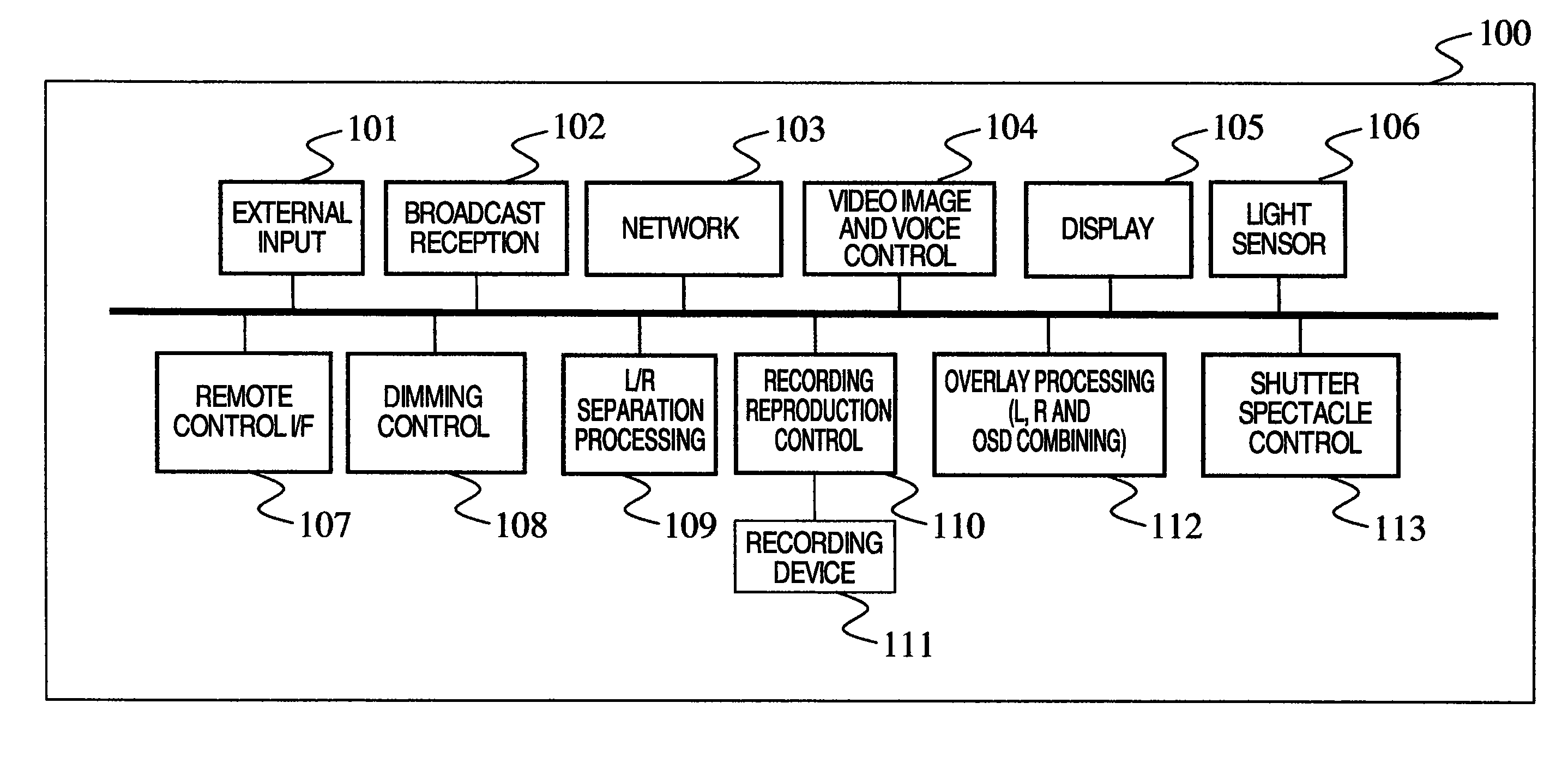
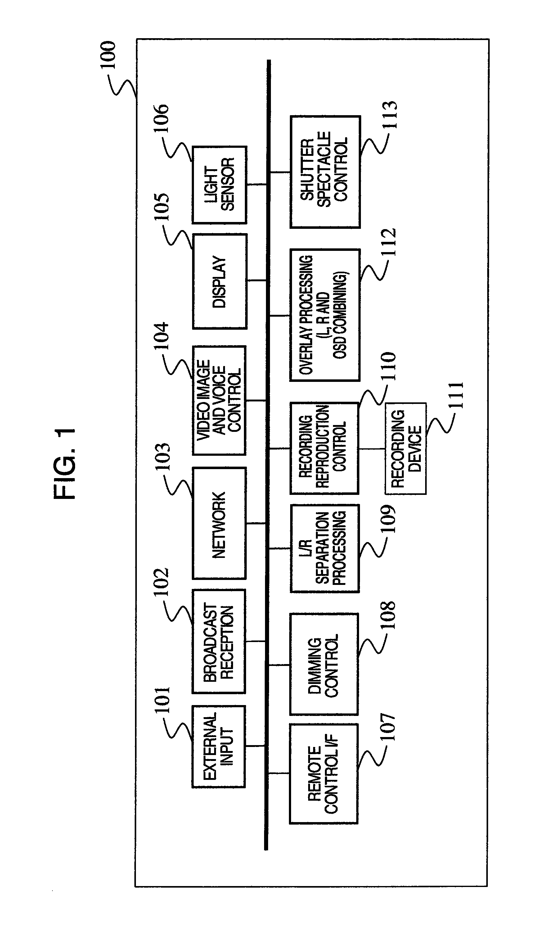
[0033]FIG. 1 is a block diagram showing an example of the configuration of a display device of Embodiment 1.
[0034]In FIG. 1, numeral 100 designates a three-dimensional display control device, 101 an external input part, 102 a broadcast reception part, 103 a network part, 104 a video and audio control part, 105 a display part, 106 a light sensor part, 107 a remote control I / F part, 108 a dimming control part, 109 a UR separation processing part, 110 a recording reproduction part, 111 a recording device, 112 an overlap processing part, and 113 a shutter spectacle control part.
[0035]External input part 101 is capable of inputting content such as video images, voice, and characters from a player device such as an optical disc or a game console. Broadcast reception part 102 can receive video, voice, or EPG (Electronic Program Guide) data or the like from radio, television, CATV (Cable Television), or th...
second embodiment
[0113]Hereinafter, Embodiment 2 will be described with reference to FIG. 11 to FIG. 13.
[0114]FIG. 11 is a block diagram showing an example of the configuration of a display device of Embodiment 2, the configuration being one in which a human detection sensor 1100 has been added to FIG. 1, the configuration example of Embodiment 1.
[0115]Human detection sensor 1100 is composed of a human sensor or a camera sensor and a microphone sensor, and detects, inside the detection area, the presence or absence of human beings, or the viewing situation, the number of viewers, viewer identities, and the like.
[0116]According to the present configuration, there is made possible a function by which the 3D display setting is automatically chosen to be “Off” in case the user is no longer present while the 3D display setting is “On”. As for this, it can be considered that, in the case where the user has some errand and has left his seat and is no longer in the viewing area during 3D display, there are ...
third embodiment
[0131]Hereinafter, Embodiment 3 is described with reference to FIG. 14 to FIG. 16.
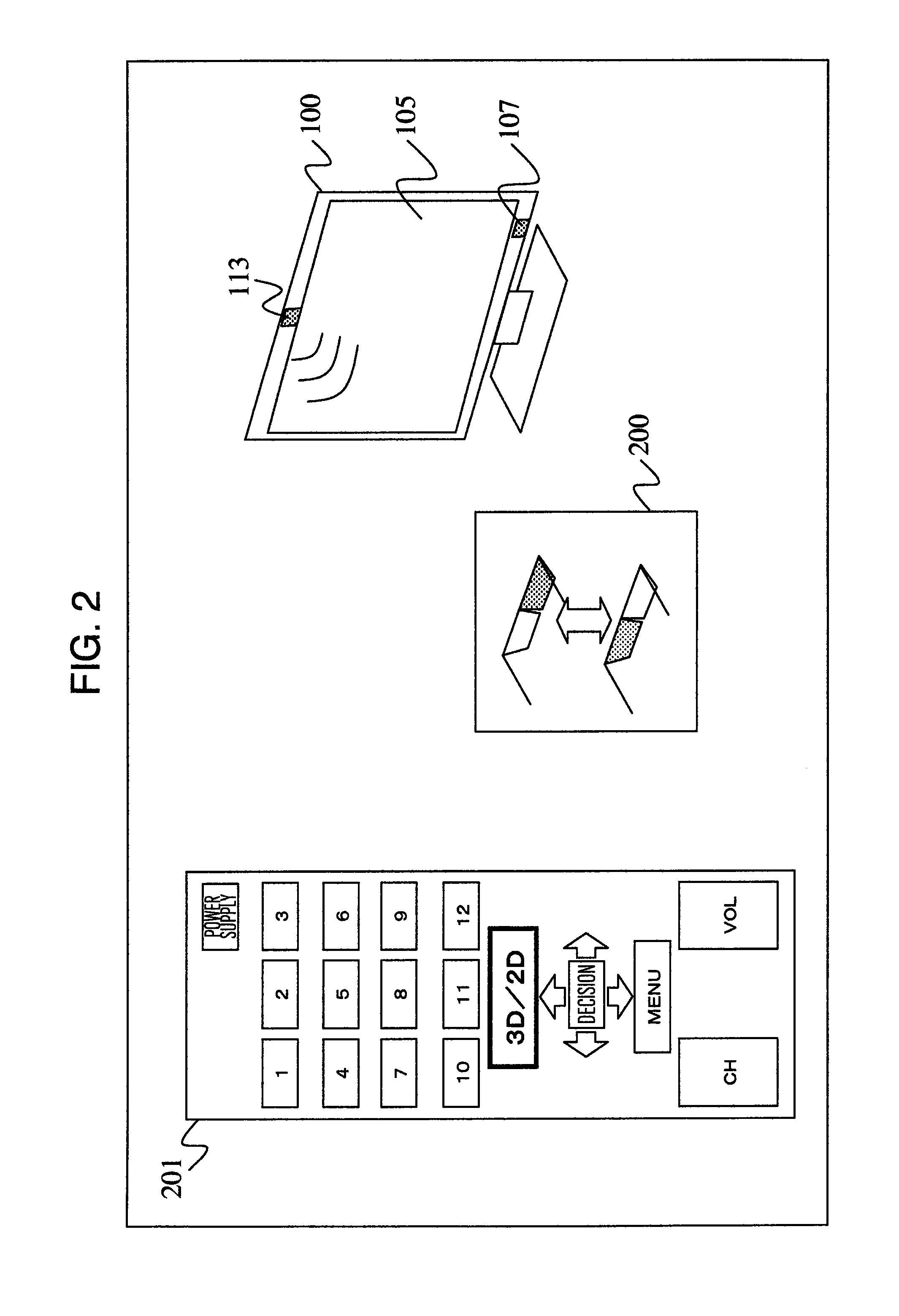
[0132]FIG. 14 is a diagram showing a utilization configuration example of a display device of Embodiment 3.
[0133]Numeral 1400 designates a pair of 3D spectacles (also called “viewing device”) used for viewing 3D video images and 1401 is a switch detecting that the user is wearing the 3D spectacles. 3D spectacles 1400 acquire synchronization from a left and right shutter opening and closing signal, from shutter opening and closing signal transmission part 113 with which three-dimensional display control device 100 is equipped, to carry out opening and closing control of the left and right shutter.
[0134]As for numeral 1401, there can be considered items like an electrostatic touch switch or a relay switch. The mechanism is one in which the switch is automatically pressed due to the fact that the user puts on the spectacles. If switch 1401 is pressed, it transmits a spectacle mounting signal to remote con...
PUM
 Abstract
Description
Claims
Application Information