Method and system for image registration and change detection

a change detection and image technology, applied in the field of image processing, can solve the problems of significant deformation of change detection performance, translation, and even slight rotation of the reference, and the significant challenges of most change detection systems, so as to improve the accuracy and complexity of local optimization, minimize the sum absolute difference (sad), and maximize correlation

Inactive Publication Date: 2011-09-15
US SEC THE ARMY THE
View PDF2 Cites 122 Cited by
  • Summary
  • Abstract
  • Description
  • Claims
  • Application Information

AI Technical Summary

Benefits of technology

[0008]The processing steps may begin with a global operation that aligns the most recently collected test image to the set of reference ones. As a global pre-processing operation, the beginning step may maximize the correlation between the reference image and the spatially translated (shifted) test image within a reasonable range and / or minimize the sum absolute difference (SAD) between the spatially translated (shifted) test image and the reference image within a reasonable range. The global pre-processing ensures that the test and the reference image roughly capture the same scene or physical area. In addition, the global pre-processing limits the size of the search area in the following local registration and change detection step; hence, it improves the accuracy as well as the complexity of the local optimization.

Problems solved by technology

There are, however, some significant challenges confronting most change detection systems.
Misalignment between the reference image and the test image results in a translation, and even slight rotation, between the reference image and the test image.
Unfortunately, the performance of a change detection system often depends on how well image registration can be achieved.
If alignment was not well performed prior to the application of the change detection algorithm, the resulting change detection performance will be significantly degraded.
In addition, the degree of misalignment between the two images usually locally varies throughout large areas.
The second challenge confronting change detection systems relates to the suppression of image signatures from common objects, which appear in both the test and reference image scenes.
In current change detection systems, however, image signatures of the same object are somewhat different in the two images due to many reasons (e.g., calibration problem, slight change in aspect angle, noise, etc.) Differences in image signatures of a common object can lead to false positives since they falsely indicate large difference signatures in the resulting change detection image.
Current state-of-the-art change detection algorithms often have difficulty in suppressing these differences since they simply detect any anomalies between the signatures of the objects which are common to the test and reference images.

Method used


Image

  • Method and system for image registration and change detection
  • Method and system for image registration and change detection
  • Method and system for image registration and change detection

Examples


Embodiment Construction

[0059]The embodiments herein and the various features and advantageous details thereof are explained more fully with reference to the non-limiting embodiments that are illustrated in the accompanying drawings and detailed in the following description. Descriptions of well-known components and processing techniques are omitted so as to not unnecessarily obscure the embodiments herein. The examples used herein are intended merely to facilitate an understanding of ways in which the embodiments herein may be practiced and to further enable those of skill in the art to practice the embodiments herein. Accordingly, the examples should not be construed as limiting the scope of the embodiments herein.

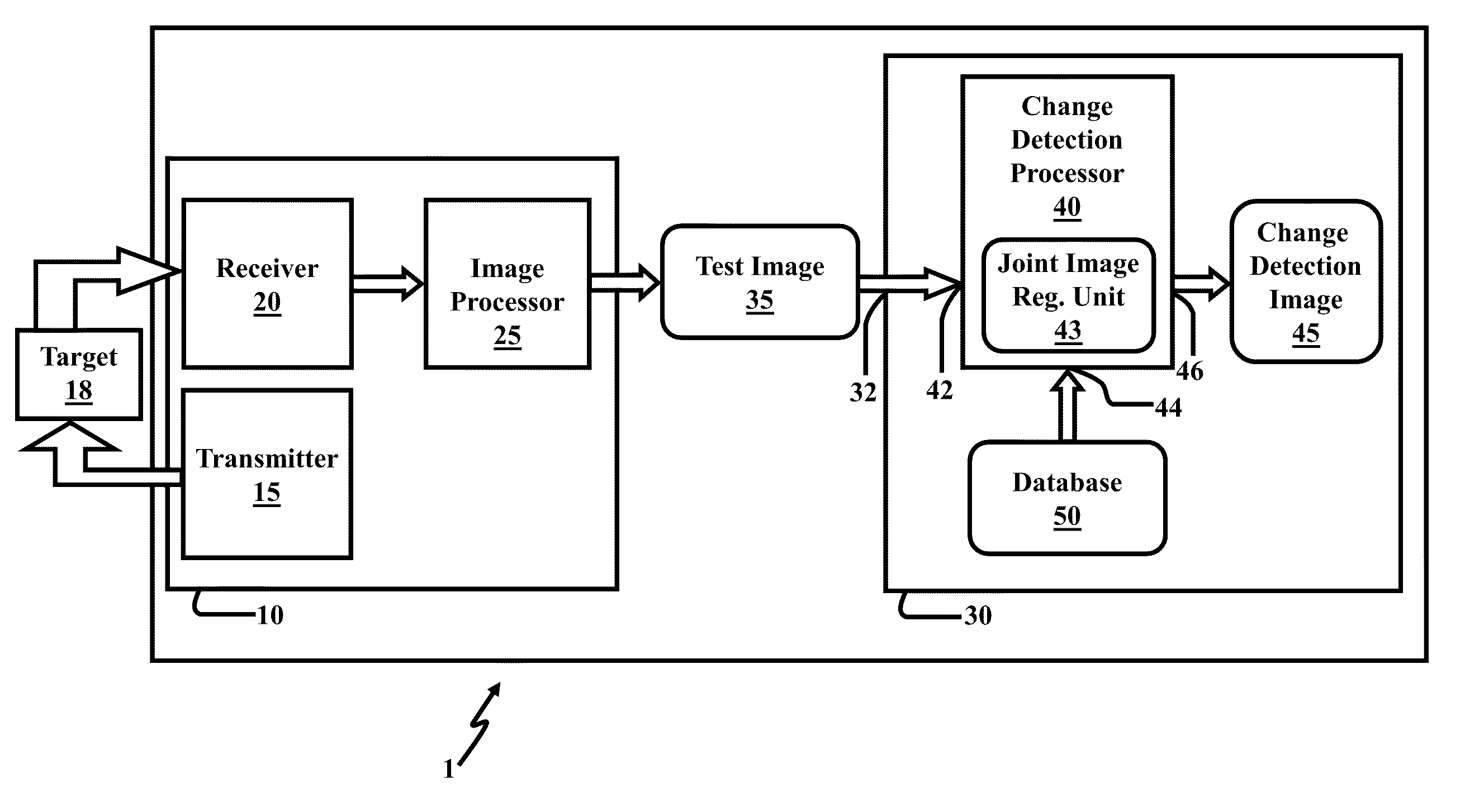
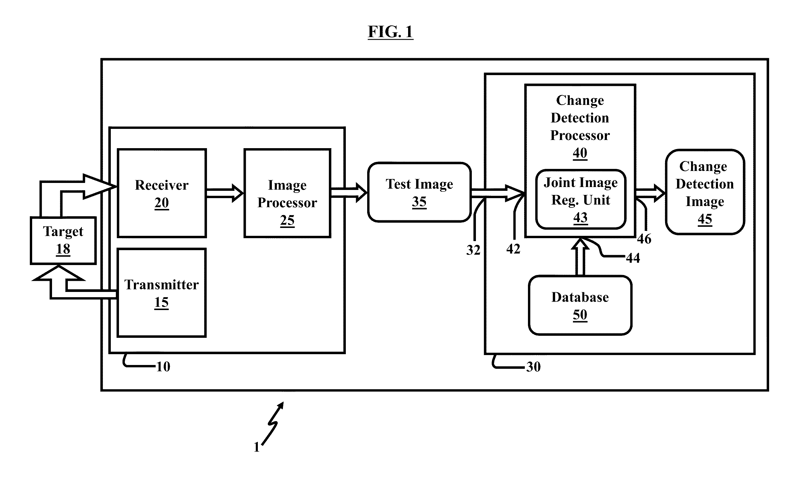
[0060]The embodiments herein provide the option of a joint image registration and change detection system and method. For example, embodiments described herein locally register reference and test images, and perform change detection analysis between the two images. Referring now to the drawings...


PUM


Abstract

A system and method for detecting changes by comparing images which cover the same physical area but are collected at different times, the system comprising: at least one input for inputting an image of a target area; the image of the target area having signatures representing outstanding features; at least one processor operating to divide the image of a target area into a plurality of target subimages; at least one memory comprising reference data comprising reference subimages taken at or near the target area at various times, the at least one processor operating to determine a sparse image representation from the reference data; the sparse image representation of the target data being a linear combination of reference data from corresponding reference subimages stored in the at least one memory; the at least one processor operating to compare the target image to the sparse image representation and to match signatures from the target image to the sparse image representation to register the images and perform change detection.

Description

STATEMENT OF GOVERNMENT INTEREST[0001]The embodiments herein may be manufactured, used, and / or licensed by or for the United States Government without the payment of royalties thereon.TECHNICAL FIELD[0002]The embodiments herein generally relate to image processing, and more particularly, to change detection techniques.BACKGROUND OF THE INVENTION[0003]Change detection is a popular and important image processing process with numerous practical applications such as medical imaging, environment, agriculture, and other remote sensing tasks. There are, however, some significant challenges confronting most change detection systems. The first challenge is image registration. For example, two images—a first image may be referred to as a reference image and a second image may be referred to as a test image in a change detection system or algorithm—are generated at different times. The reference image and the test image, however, are usually not aligned with each other, since the imaging platf...

Claims


Application Information

Patent Timeline
Patent Type & Authority Applications(United States)
IPC IPC(8): G06K9/68G06V20/13
CPCG06K9/6244G06K9/6249G06T7/2053G06K9/0063G06T2207/20221G06T2207/20224G06T2207/20021G06T7/254G06V20/13G06V10/7715G06F18/2136G06F18/21345
Inventor NGUYEN, LAM HUYTRAN, TRAC D.
Owner US SEC THE ARMY THE
Why Eureka
Try Eureka