Electrical connector

a technology of electric connectors and connectors, applied in the direction of fixed connections, coupling device connections, engagement/disengagement of coupling parts, etc., can solve the problems of increasing the thickness of constitutive parts, increasing the number of assembling steps and time, and increasing the thickness of flat circuit devices. , to achieve the effect of reducing production costs, reducing assembling steps and time, and reducing siz

Active Publication Date: 2011-09-15
DAIICHI SEIKO CO LTD
View PDF13 Cites 4 Cited by
  • Summary
  • Abstract
  • Description
  • Claims
  • Application Information

AI Technical Summary

Benefits of technology

[0012]Accordingly, it is an object of the present invention to provide an electrical connector which is operative to function as a plug type electrical connector constituted to include a connectively engaging protrusion formed with a part of a flat circuit device, such as an FPC or FFC, on which a plurality of contacting terminals are arranged, and which avoids the aforementioned disadvantages or problems encountered with the prior art.
[0013]Another object of the present invention is to provide an electrical connector which is operative to function as a plug type electrical connector constituted to include a connectively engaging protrusion formed with a part of a flat circuit device, such as an FPC or FFC, on which a plurality of contacting terminals are arranged, and with which, at least, a size in a direction of the thickness of the flat circuit device can be reduced, constitutive parts can be reduced in number and assembling steps and time can be reduced.
[0014]A further object of the present invention is to provide an electrical connector which is function as a plug type electrical connector constituted to include a connectively engaging protrusion formed with a part of a flat circuit device, such as an FPC or FFC, on which a plurality of contacting terminals are arranged, and in which each of structural members or parts is not required to be processed with extremely high precision.

Problems solved by technology

Accordingly, in the plug type electrical connector thus proposed previously, at least, there have been disadvantages that a size in a direction of the thickness of the flat circuit device is increased, the constitutive parts are increased in number, the assembling steps and time are increased, the production cost is increased and so on.
Further, in the plug type electrical connector thus proposed previously, there has been an additional problem that, since various structural members or parts are positioned with reference to the insulated housing, the insulated housing is required to be processed with extremely high precision.
Therefore, it is feared that each of the contacting terminals through which signals are transmitted is varied in its characteristic impedance so that impedance-mismatching is brought about on each of the contacting terminals.

Method used


Image

  • Electrical connector
  • Electrical connector
  • Electrical connector

Examples


first embodiment

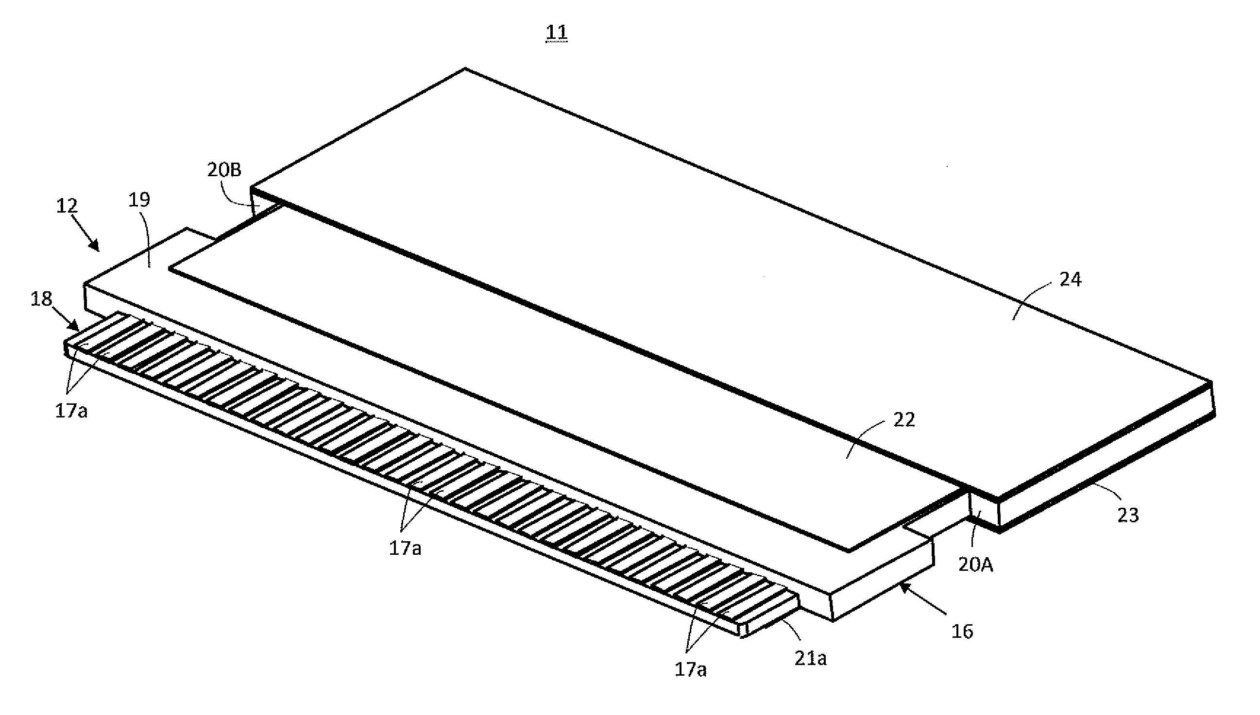
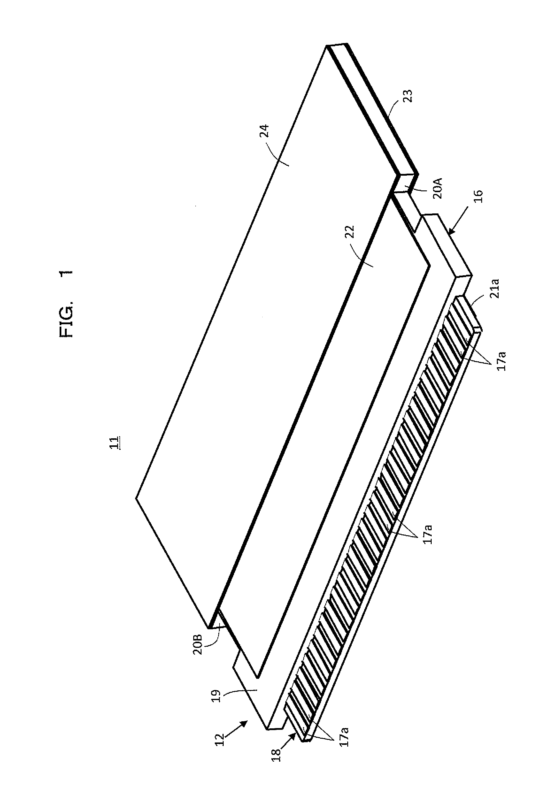
[0060]FIG. 1 shows a flat circuit device 11 having an end portion 12 thereof which constitutes one of constitutive elements of electrical connector according to the present invention. The flat circuit device 11 is constituted with an FFC, for example.

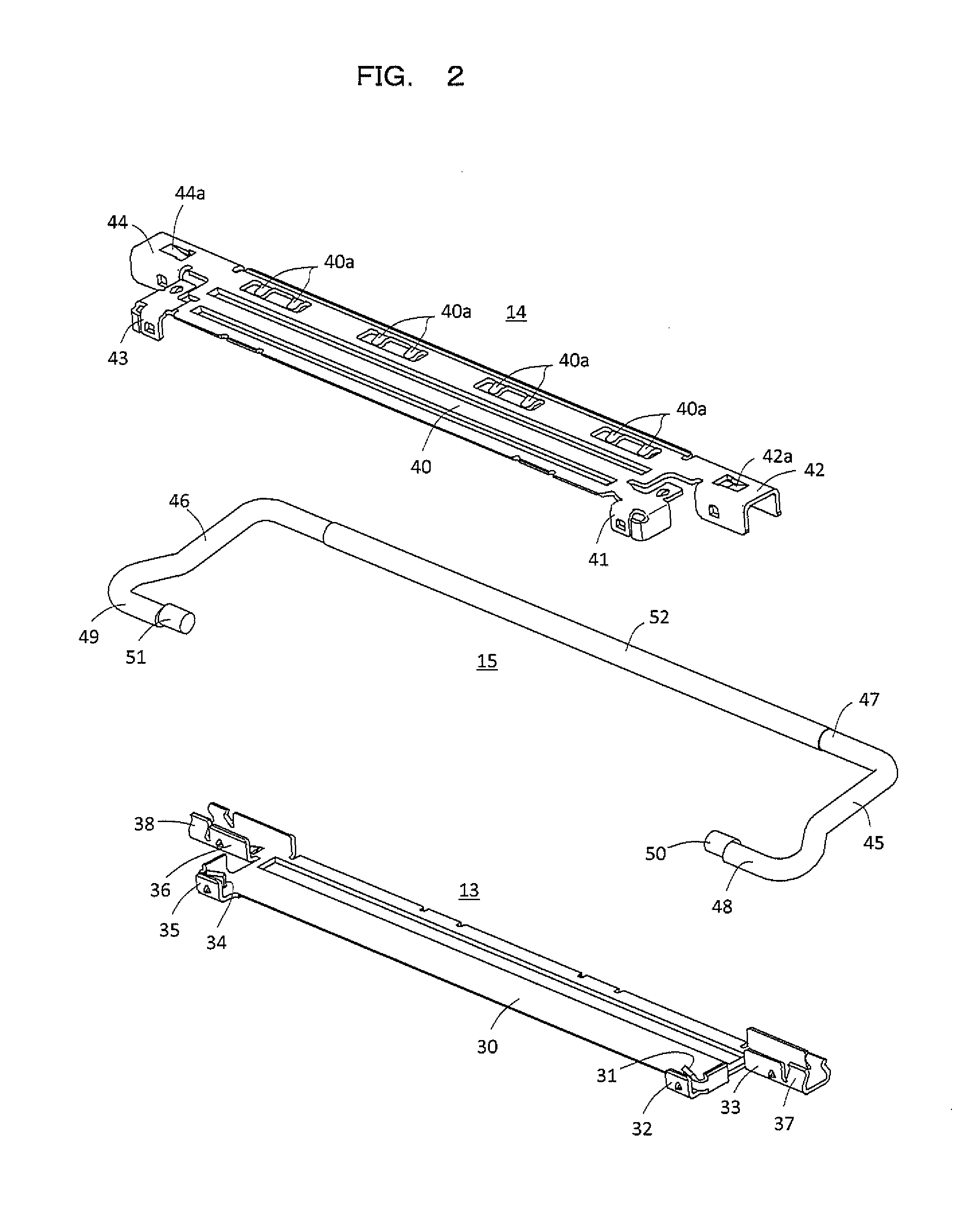
[0061]FIG. 2 shows conductive shells 13 and 14 and a manipulative lever 15 which constitutes, together with the end portion 12 of the flat circuit device 11, the constitutive elements of the first embodiment of electrical connector according to the present invention.

[0062]As shown also in FIGS. 3 to 6, the flat circuit device 11 is provided with a board-shaped insulated base 16 and the end portion 12 of the flat circuit device 11 includes the board-shaped insulated base 16. As shown in FIG. 6 which shows a cross sectional view taken along line VI-VI in FIG. 4, a plurality of strip-shaped conductors 17 for transmitting signals arranged substantially in parallel with each other, a cross section of one of which is shown in FIG. 6, are buri...

second embodiment

[0103]FIG. 22 shows conductive shells 71 and 72 and a pair of connecting members 73A and 73B for connecting the conductive shell 71 with the conductive shell 72, which constitute constitutive elements of electrical connector according to the present invention, together with the end portion 12 of the flat circuit device 11 shown in FIG. 1 and the manipulative lever 15 shown in FIG. 2.

[0104]The conductive shells 71 and 72 and the connecting members 73A and 73B through which the conductive shells 71 and 72 are connected with each other are incorporated as a single element and formed by means of punching and bending a resilient metallic plate, for example.

[0105]The conductive shell 71 is formed in the same manner as the conductive shell 13 shown in FIGS. 2 and 7 to have a slender plate portion 75. A pressing tongue 76 and engaging portions 77 and 78 are provided on one of end portions of the slender plate portion 75 opposite to each other and a pressing tongue 79 and engaging portions 8...


PUM


Abstract

An electrical connector comprising an end portion of a flat circuit device which forms a connectively engaging protrusion on which a plurality of contacting terminals are arranged and a supporting board portion for supporting the connectively engaging protrusion, and first and second conductive shells having respectively first and second plate portions opposite to each other with the supporting board portion between, wherein the first conductive shell is attached to the supporting board portion with the first plate portion thereof covering directly a first surface of the supporting board portion and the second conductive shell is attached also to the supporting board portion with the second plate portion thereof covering directly a second surface opposite to the first surface of the supporting board portion, so that the first and second conductive shells are operative to hold the connectively engaging protrusion supported with the supporting board portion for causing the same to engage with a mating electrical connector.

Description

BACKGROUND OF THE INVENTION[0001]1. Field of the Invention[0002]The present invention relates to an electrical connector for a flat circuit device, such as a flexible printed circuit board (hereinafter, referred to as an FPC), a flexible flat cable assembly (hereinafter, referred to as an FFC) or the like, and more particularly to an improvement in an electrical connector with which contacting terminals provided on a flat circuit device are put in engagement with a mating electrical connector mounted on a main circuit board, such as a solid printed circuit board, to be connect electrically with the same.[0003]2. Description of the Prior Art[0004]A relatively small-sized flat circuit device, such as a relatively small-sized FPC or FFC, used in various kinds of electronic apparatus is often connected electrically with a solid printed circuit board, on which various electrical parts are directly mounted, through an electrical connector which is fixed to and connected electrically with ...

Claims


Application Information

Patent Timeline
Patent Type & Authority Applications(United States)
IPC IPC(8): H01R12/51
CPCH01R12/775H01R12/88H01R12/79H01R12/77
Inventor IKARI, HIROHARUISHIMARU, MASAO
Owner DAIICHI SEIKO CO LTD
Why Eureka
Try Eureka