Vehicle with removable auxiliary power system

a technology of auxiliary power system and vehicle, which is applied in the direction of battery/fuel cell control arrangement, electric propulsion mounting, battery/fuel cell propulsion, etc., can solve the problems of additional weight of hybrid power supply when, limited range of vehicle, weight/cost penalty, etc., and achieves easy installation and removal, extended vehicle range, and high energy demand

Inactive Publication Date: 2011-09-22
HUSS MICHAEL A +1
View PDF7 Cites 41 Cited by
  • Summary
  • Abstract
  • Description
  • Claims
  • Application Information

AI Technical Summary

Benefits of technology

[0007]It is therefore an object of the present invention to provide an electric vehicle with the facilities to accept the intermittent instillation of a portable power generator for the purpose of supplying energy to the batteries to extend the range of the vehicle and or to accommodate high energy demand accessories such as headlights and air conditioning which can be easily installed and removed.

Problems solved by technology

Electric vehicles primary drawback is their limited range with weight / cost penalties as battery capacity increases and hybrid vehicles main disadvantage is the additional weight of the hybrid power supply when not required such as on short trips well within the range of the battery capacity.
Although prior art discloses a removable hybrid system, there is no known prior art which addresses the aforementioned dichotomy between a lack of range for battery operation alone and unnecessary weight in hybrid vehicles for short range driving in a manner which economically and practically combines the advantages of battery operation and hybrid operation.
Each prior art removable power supply detailed above, although appropriate for their intended use, include unnecessary complexity for a simple hybrid vehicle.

Method used


Image

  • Vehicle with removable auxiliary power system
  • Vehicle with removable auxiliary power system
  • Vehicle with removable auxiliary power system

Examples


Embodiment Construction

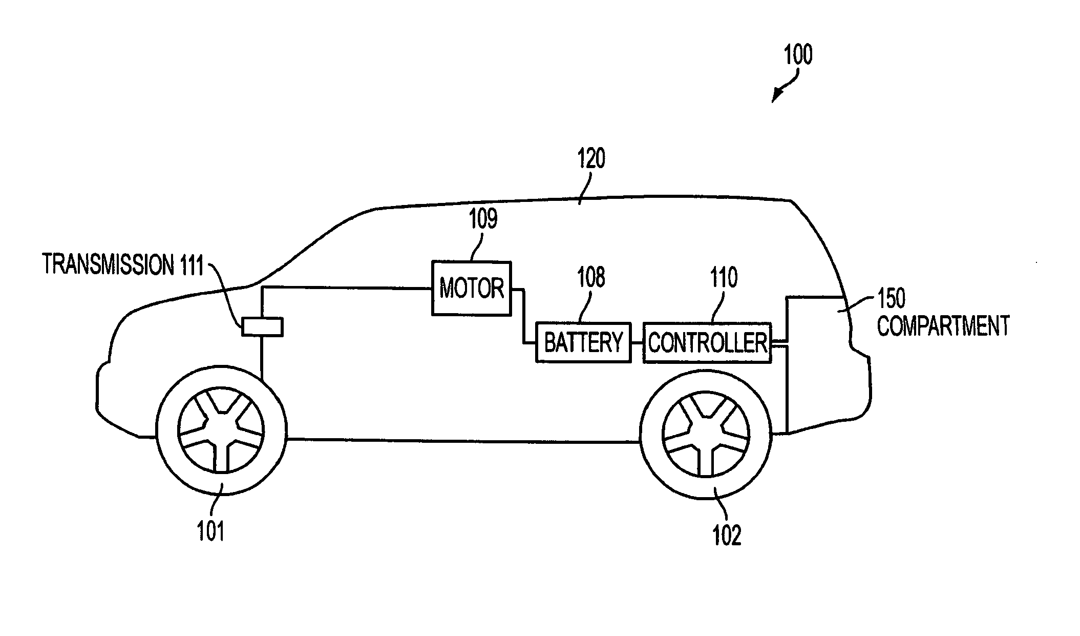
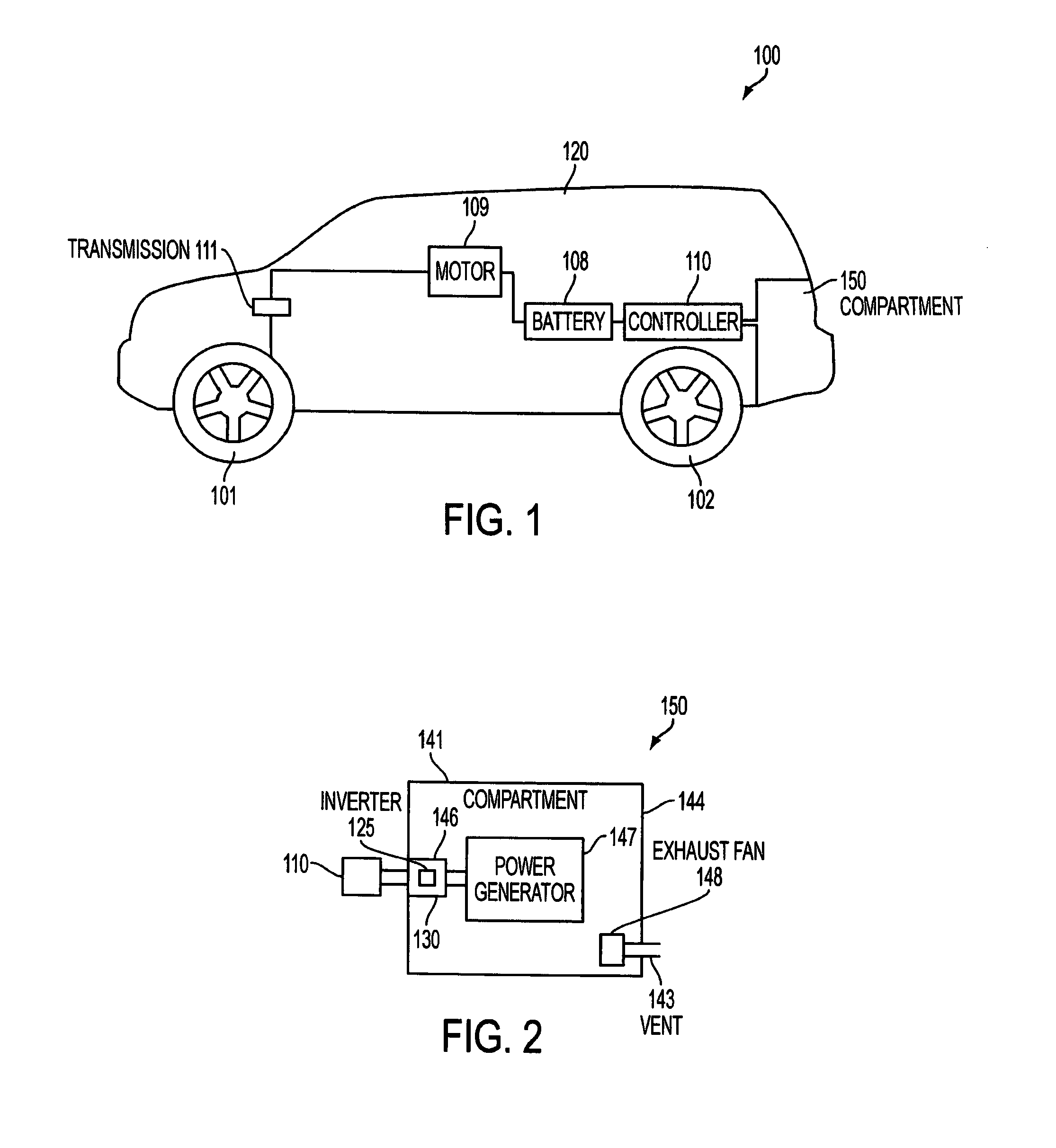
[0016]An electric vehicle illustrated in FIG. 1 is structured and modified to enable the use of a removable power generator system. The vehicle 100 includes wheels 101 and 102. In the illustration the wheels 101 are the “driven” wheels as they are shown connected to the battery 108. Wheels 101 use the power of battery 108 to drive the electric motor 109 and transmission 111. While only two wheels are shown as driven in the embodiment of FIG. 1, it should be appreciated that all four wheels could be driven and that a different number of wheels could be driven depending on the type of vehicle. The vehicle 100 includes a compartment 150 separate from the remainder of the interior 120. It is the compartment 150 which serves as the container for supplementing the power of the vehicle through use of a hybrid system and / or battery packs isolated from the passenger compartment and providing power through a controller 110 which functions to regulate charging of battery 108 and controls the p...


PUM


Abstract

An electric and hybrid vehicle configuration with removable auxiliary power supply is disclosed which provides a flexible configuration for, on the one hand, allowing on demand increased range and additional power for accessories and / or increased performance when the auxiliary power supply is easily inserted in the vehicle to charge the battery in an electric vehicle and on the other hand, allowing for weight reduction and increased storage capacity or increased battery capacity when the power supply is removed. In another embodiment, the removable auxiliary power supply may drive the vehicle either separately or in conjunction with the charging of the vehicle main battery to thereby provide a hybrid vehicle configuration.

Description

BACKGROUND OF THE INVENTION[0001]1. Field of the Invention[0002]The present invention relates to electric and hybrid vehicles and particularly to auxiliary power systems for the vehicles.[0003]2. Description of the Background Art[0004]The popularity of alternatively powered vehicles has led to the building and patenting of numerous systems involving electric and hybrid vehicles. Each of these types comes with inherent disadvantages. Electric vehicles primary drawback is their limited range with weight / cost penalties as battery capacity increases and hybrid vehicles main disadvantage is the additional weight of the hybrid power supply when not required such as on short trips well within the range of the battery capacity. Normal commutes in the United States average approximately 35 miles which could be accomplished economically within the range of many batteries so that the unnecessary weight of the power supply of a hybrid vehicle serves as a hindrance for such distances and occupie...

Claims


Application Information

Patent Timeline
Patent Type & Authority Applications(United States)
IPC IPC(8): B60K6/20B60K1/04B60K8/00
CPCB60K1/04B60K6/46B60K2001/0416Y02T10/6217B60L11/123B60L11/1822Y02T90/14B60L2270/40Y02T10/7077Y02T10/7005Y02T10/7072Y02T90/34Y02T90/124B60L11/1881B60L50/61B60L53/80B60L58/30Y02T10/62Y02T10/70Y02T90/40Y02T90/12
Inventor HUSS, MICHAEL A.VOLLERS, ROBERT D.
Owner HUSS MICHAEL A
Why Eureka
Try Eureka