
Traction System and an Elevator Arrangement Incorporating Said Traction System

a technology of traction system and elevator arrangement, which is applied in the direction of vehicle/pulley ropes, textile cables, applications, etc., can solve the problems of relatively severe shear stress on the elastomer material of the flat belt, and achieve the effect of wide tension drum and easy assembly

Inactive Publication Date: 2011-09-22
CONTITECH ANTRIEBSSYST
View PDF27 Cites 8 Cited by
  • Summary
  • Abstract
  • Description
  • Claims
  • Application Information

AI Technical Summary

Benefits of technology

[0015]It is an object of the invention to provide a traction system of the type described above which is simple to handle, in which high pulling forces can be transmitted and in which the pulling means allows the use of a drive unit of narrower construction than that in the known belt systems.

Problems solved by technology

The force that can be transmitted is thus somewhat greater than in the case of an unprofiled flat belt but, here too, the zone of force transmission between the traction sheave and the pulling means is still a significant distance from the tension members, with the result that the elastomer material of the flat belt is subjected to relatively severe shear stress.

Method used


Image

  • Traction System and an Elevator Arrangement Incorporating Said Traction System
  • Traction System and an Elevator Arrangement Incorporating Said Traction System
  • Traction System and an Elevator Arrangement Incorporating Said Traction System

Examples


Embodiment Construction

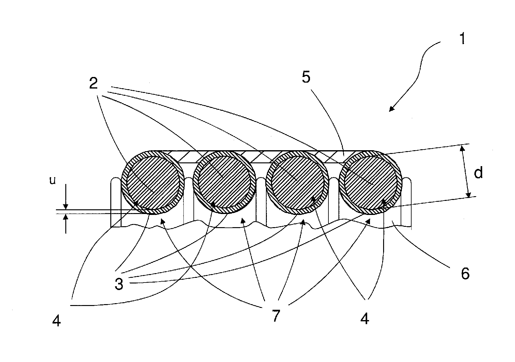
[0051]The composite rope 1 shown in cross section in FIG. 1 has four individual ropes 2 having a diameter (d), which are each encased with a jacket 3 having a thickness (u) composed of an elastomer to yield tension members 4.

[0052]The tension members 4 are tightly connected to one another by a connecting layer 5 on one side, the connection being produced by vulcanizing the elastomer jacket 3 to the connecting layer 5 and the individual ropes 2. The composite rope 1 rests on a traction sheave 6, the tension members 4 engaging in grooves 7 of the traction sheave 6. The connecting layer 5 is arranged on the side of the tension members 4 which faces away from the traction sheave 6.

[0053]The tension members 4 engage in the grooves 7 of the traction sheave 6 in such a way that the individual ropes 2 of the tension members 4 penetrate by approximately 50% of the diameter of the individual ropes into the grooves 7.

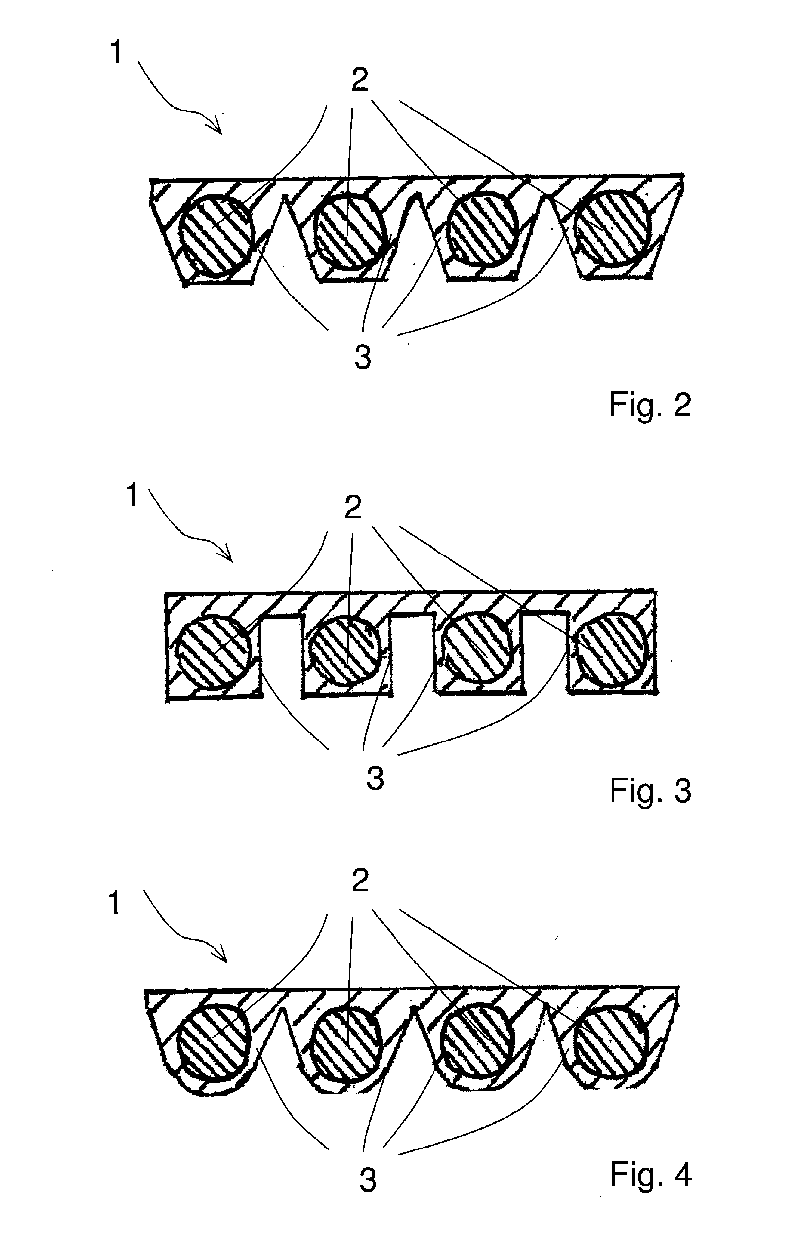
[0054]FIGS. 2, 3 and 4 show composite ropes 1, the jacket 3 of the individual...


PUM


Abstract

A traction system includes a composite rope (1), especially for an elevator. The composite rope (1) is driveable by a traction sheave (6). The traction system has a composite rope that is easy to handle, whereby high traction forces can be transferred, and the composite rope enables a narrower drive unit than known belt technology. To this end, the composite rope has parallel individual tension members (4) surrounded by an elastomer material which are interconnected by an elastomer connecting layer (5) on one side, and the tension members (4) engage in corresponding grooves (7) of the traction sheave (6). The penetration depth of the individual ropes (2) of the tension members (4) in the grooves of the traction sheave (6) is at least 25% of the diameter (d) of the individual ropes (2).

Description

CROSS REFERENCE TO RELATED APPLICATIONS[0001]This application is a continuation application of international patent application PCT / EP 2009 / 062503, filed Sep. 28, 2009, designating the United States and claiming priority from German application 10 2008 037 538.1, filed Nov. 10, 2008, and the entire content of both applications is incorporated herein by reference.FIELD OF THE INVENTION[0002]The invention relates to a traction system, especially for an elevator, the traction system includes at least the following components, namely at least one pulling means and at least one traction sheave. The invention also relates to an elevator arrangement incorporating the traction system.BACKGROUND OF THE INVENTION[0003]Traction systems for lifts or elevators are known per se. Ropes, but also belts, are frequently used as pulling means, with both flat belts and V-ribbed belts or even toothed belts being used as belts.[0004]Where ropes are used as pulling means, each individual rope is clearly a...

Claims


Application Information

Patent Timeline
IPC IPC(8): B66B7/08F16G11/00
CPCB66B15/04Y10T24/3909B66B7/062
Inventor GOSER, HUBERT
Owner CONTITECH ANTRIEBSSYST
Learn More