

User identification based on body-coupled communication
a technology of body-coupled communication and user identification, which is applied in the direction of near-field systems using receivers, instruments, transmissions, etc., can solve the problems of slow system access, inability to fully secure the system, and reduced availability, so as to achieve reliable user identification and fast system access
- Summary
- Abstract
- Description
- Claims
- Application Information
AI Technical Summary
Benefits of technology
Problems solved by technology
Method used
Image

Examples
first embodiment
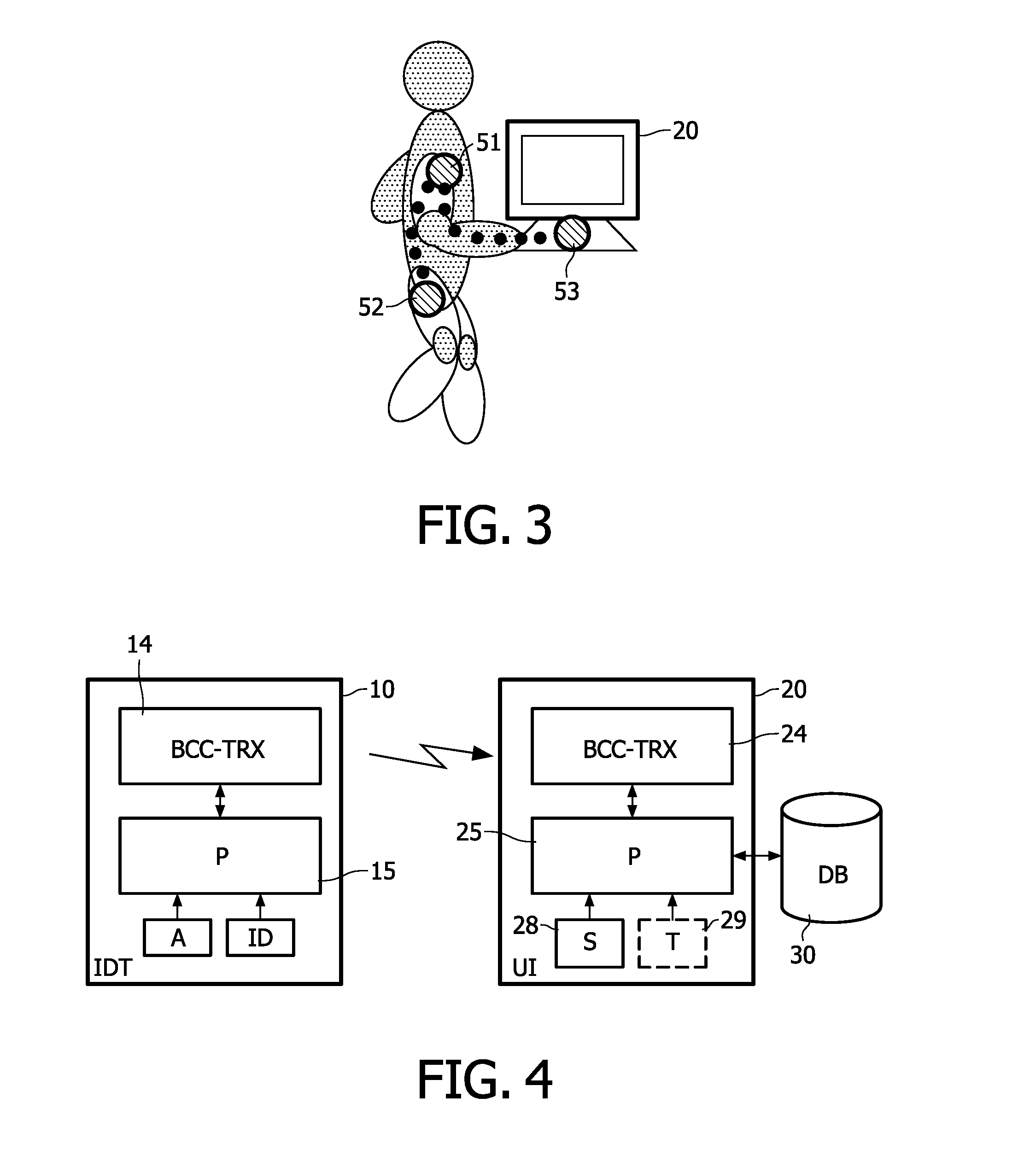
[0044]FIG. 4 shows a schematic block diagram of an identification system according to a The identification system comprises IdTag (IDT) 10 and a user interface (UI) 20, such as a touch screen device. The IdTag 10 comprises a BCC transceiver (BCC-TRX) 14 for transmitting and receiving BCC signals via coupling electrodes (not shown) over a BCC channel formed by the body of a user who wears the IdTag 10. Additionally, a processing device or processor (P) 15 is provided in the IdTag 10, which is coupled to the BCC transceiver 14 and which has access to a user ID and an authentication information (A), e.g., username and password.
[0045]The user interface (UI) 20 also comprises a BCC transceiver (BCC-TRX) 24 for transmitting and receiving BCC signals via coupling electrodes (not shown) over a BCC channel formed by the body of a user who touches or at least approaches the user interface 20. Additionally, a processing device or processor (P) 25 is provided in the user interface 20, which is...
second embodiment
[0056]FIG. 5 shows a schematic block diagram of an IdTag with authentication option according to a The IdTag 10 comprises a BCC transceiver (BCC-TRX) 34 for transmitting and receiving BCC signals via coupling electrodes (not shown) over a BCC channel formed by the body of a user who wears the IdTag. Additionally, a processing device or processor (P) 35 is provided in the IdTag, which is coupled to the BCC transceiver 34. The processor 35 has access to a look-up table (LUT) 33 which stores user data which identifies users authorized to use the IdTag. The look-up table may be provided in any kind of detachable or non-detachable memory device. Furthermore, an authenticator (AUT) 36 is provided which receives user authentication information e.g. from an optional keyboard 32 or any other kind of input device, e.g. biometric sensor or the like, for inputting user authentication information. The authenticator 36 controls the processor 35 to activate / enable or deactivate / disable the IdTag ...
third embodiment
[0064]As an additional or alternative option a user can wear one or more, i.e. between 1 and t, additional authentication tags (AuthTags) on his body to ensure that the IdTag is still on the body.
[0065]FIG. 8 shows a flow diagram of a user presence identification procedure according to the third embodiment.
[0066]In step S200 user authentication is performed. After the user has entered the authentication password and authentication was successful, the BCC transceiver of the IdTag sends a discovery message via the BCC channel on the body of the user (step S210). All AuthTags on the body respond with a message containing their address. These responses are received in step S220. In step S230 the IdTag detects the addresses in the received responses. Then, in step S240, the IdTag creates a table containing all these addresses. This address table may be stored for example in the look-up table 33 of the IdTag shown in FIG. 5.
[0067]The IdTag (e.g. under control of the detector 37 of FIG. 5...
PUM
 Abstract
Description
Claims
Application Information