Image processing device, display system, electronic apparatus, and image processing method

Active Publication Date: 2011-09-22
SEIKO EPSON CORP
View PDF7 Cites 18 Cited by
  • Summary
  • Abstract
  • Description
  • Claims
  • Application Information

AI Technical Summary

Benefits of technology

[0010]An advantage of some aspects of the invention is that it provides an image processing device, a display system, an electronic apparatus, and an image

Problems solved by technology

However, when the time in which the same light-emitting element is lit with the same brightness lasts longer such as when a still image is displayed for a long time, a so-called burn-in phenomenon occurs even in the display pan

Method used


Image

  • Image processing device, display system, electronic apparatus, and image processing method
  • Image processing device, display system, electronic apparatus, and image processing method
  • Image processing device, display system, electronic apparatus, and image processing method

Examples


Example

[0047]Hereinafter, exemplary embodiments of the invention will be described in detail with reference to the accompanying drawings. The following embodiments are not intended to limit the details of the invention described in the appended claims. All the configurations described below are not essential to accomplish the above-mentioned advantages.

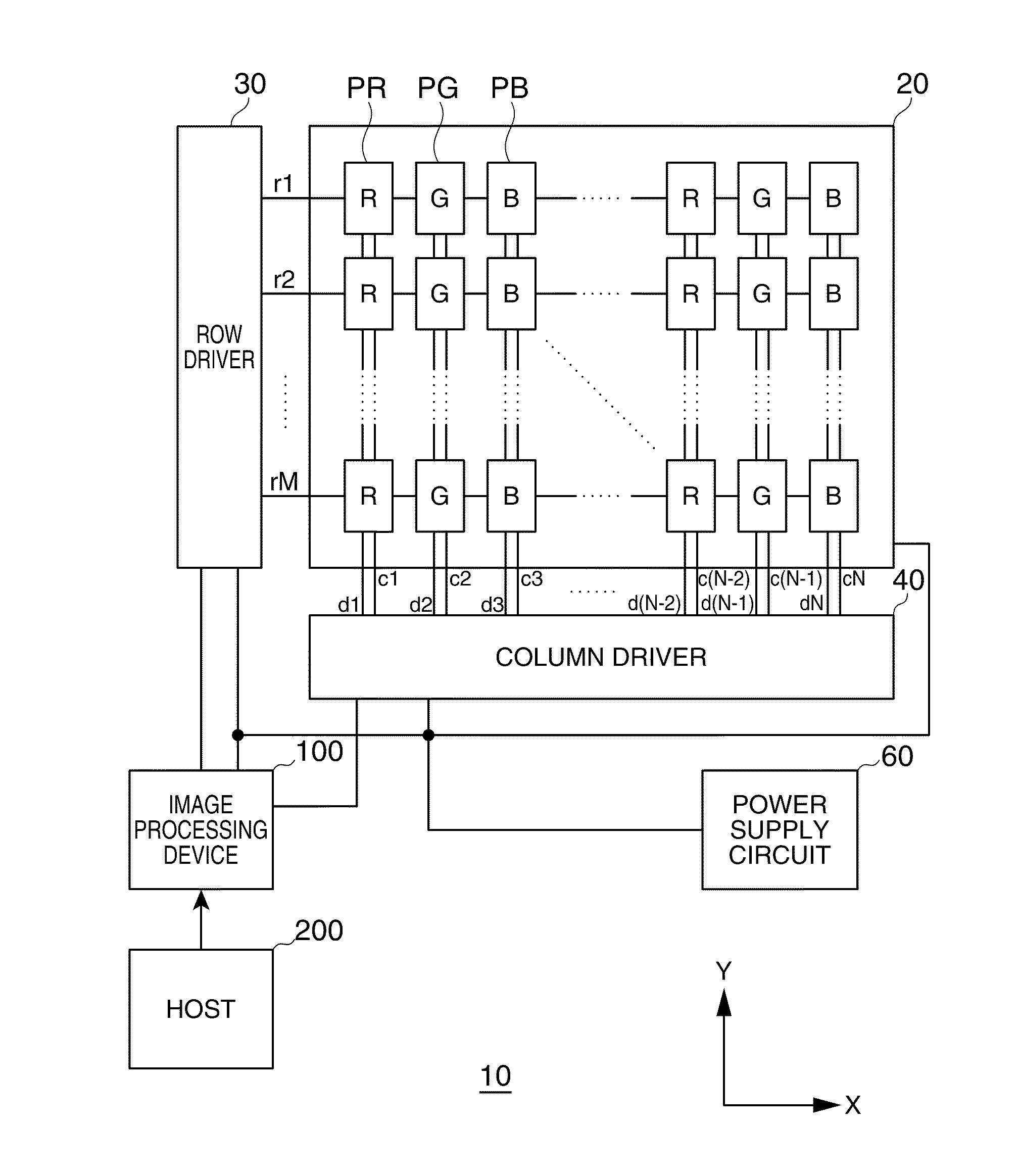
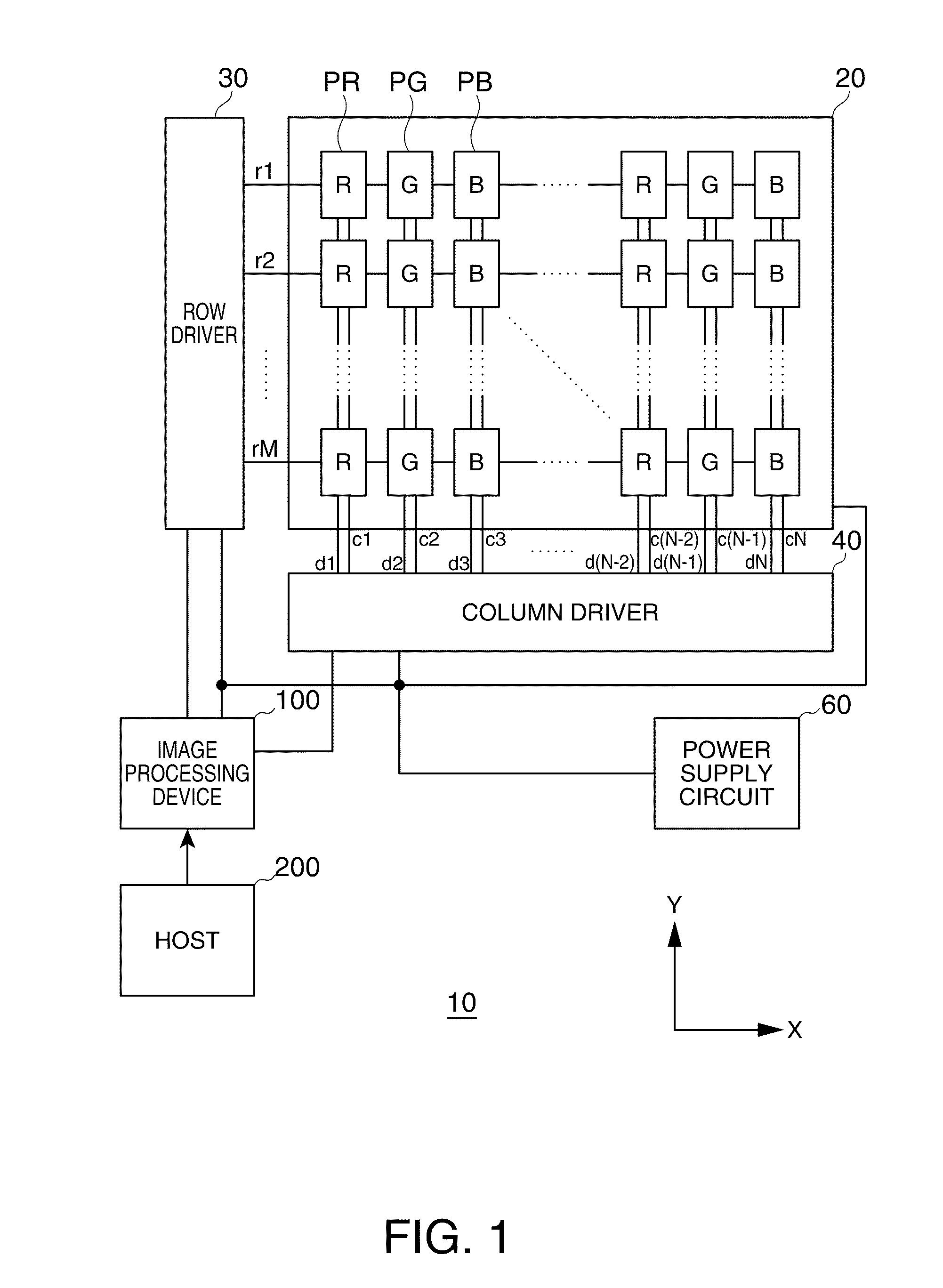
[0048]FIG. 1 is a block diagram illustrating the configuration of a display system according to an embodiment of the invention. The display system includes a display panel (light-emitting panel) using OLEDs which are light-emitting elements as display elements. Each OLED is driven by a row driver and a column driver on the basis of image data and a display timing control signal generated by an image processing device.

[0049]The display system 10 shown in FIG. 1 includes a display panel 20, a row driver 30, a column driver 40, a power supply circuit 60, an image processing device 100, and a host 200. In the display panel 20, plural data signal...


PUM


Abstract

An image processing device performing a frame rate control a display timing control signal corresponding to an image data, includes: a brightness distribution generating unit that generates a brightness distribution on the basis of the image data; an image type determining unit that determines a type of an image on the basis of the brightness distribution; and a frame rate control unit that performs frame rate control corresponding to the determined image type.

Description

[0001]The entire disclosure of Japanese Patent Application No. 2010-062096, filed Mar. 18, 2010, is expressly incorporated by reference herein.BACKGROUND[0002]1. Technical Field[0003]An aspect of the present invention relates to an image processing device, a display system, an electronic apparatus, and an image processing method.[0004]2. Related Art[0005]Recently, LCD (Liquid Crystal Display) panels using liquid crystal elements as display elements or display panels (display devices) using organic light emitting diodes (hereinafter, abbreviated as “OLED”) (light-emitting elements in a broad sense) as display elements have been widely spread. The OLED has a higher response speed than that of the liquid crystal element and improves the contrast ratio. By using the display panel in which such OLEDs are arranged in a matrix shape, it is possible to display an image with a large viewing angle and high image quality.[0006]However, when the time in which the same light-emitting element is ...

Claims


Application Information

Patent Timeline
IPC IPC(8): G09G5/10
CPCG09G3/2025G09G3/3225G09G2360/16G09G2320/10G09G2320/046G09G3/007G09G3/20G09G3/30
Inventor KIKUTA, KAZUTO
Owner SEIKO EPSON CORP
Why Eureka
Try Eureka