Stereoscopic imaging apparatus

Active Publication Date: 2011-09-22
FUJIFILM CORP
View PDF6 Cites 27 Cited by
  • Summary
  • Abstract
  • Description
  • Claims
  • Application Information

AI Technical Summary

Benefits of technology

[0044]With this configuration, it is possible to further decrease the size of a stereoscopic imaging apparatus more than a stereoscopic imaging apparatus using a plurality of image sensors.
[0045]As described above, according to the present invention, since contrast AF is used in the stereoscopic imaging apparatus, it is possible to obviate disadvantages of ph

Problems solved by technology

Moreover, in the stereoscopic imaging apparatus of the related art, since images (left viewpoint image and right viewpoint image) for phase-difference AF are obtained in advance, the contrast AF will not be performed.
However, since the phase-difference AF method performs focus detection from the phase difference bet

Method used


Image

  • Stereoscopic imaging apparatus
  • Stereoscopic imaging apparatus
  • Stereoscopic imaging apparatus

Examples


first embodiment

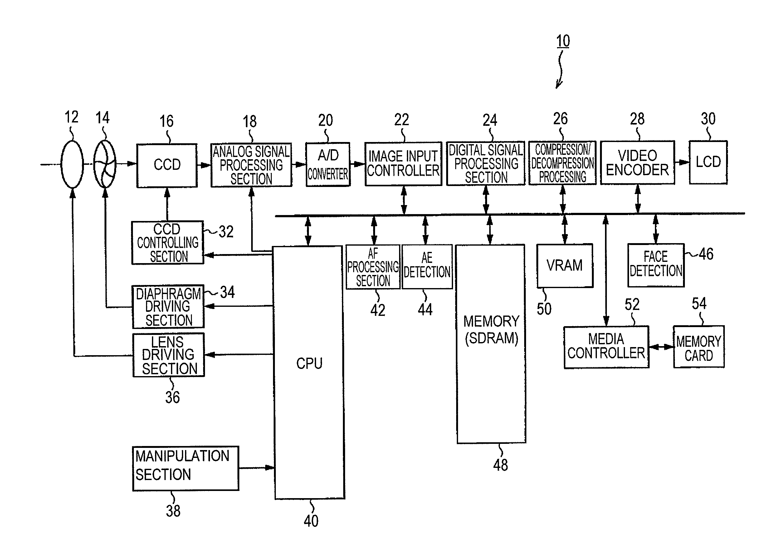
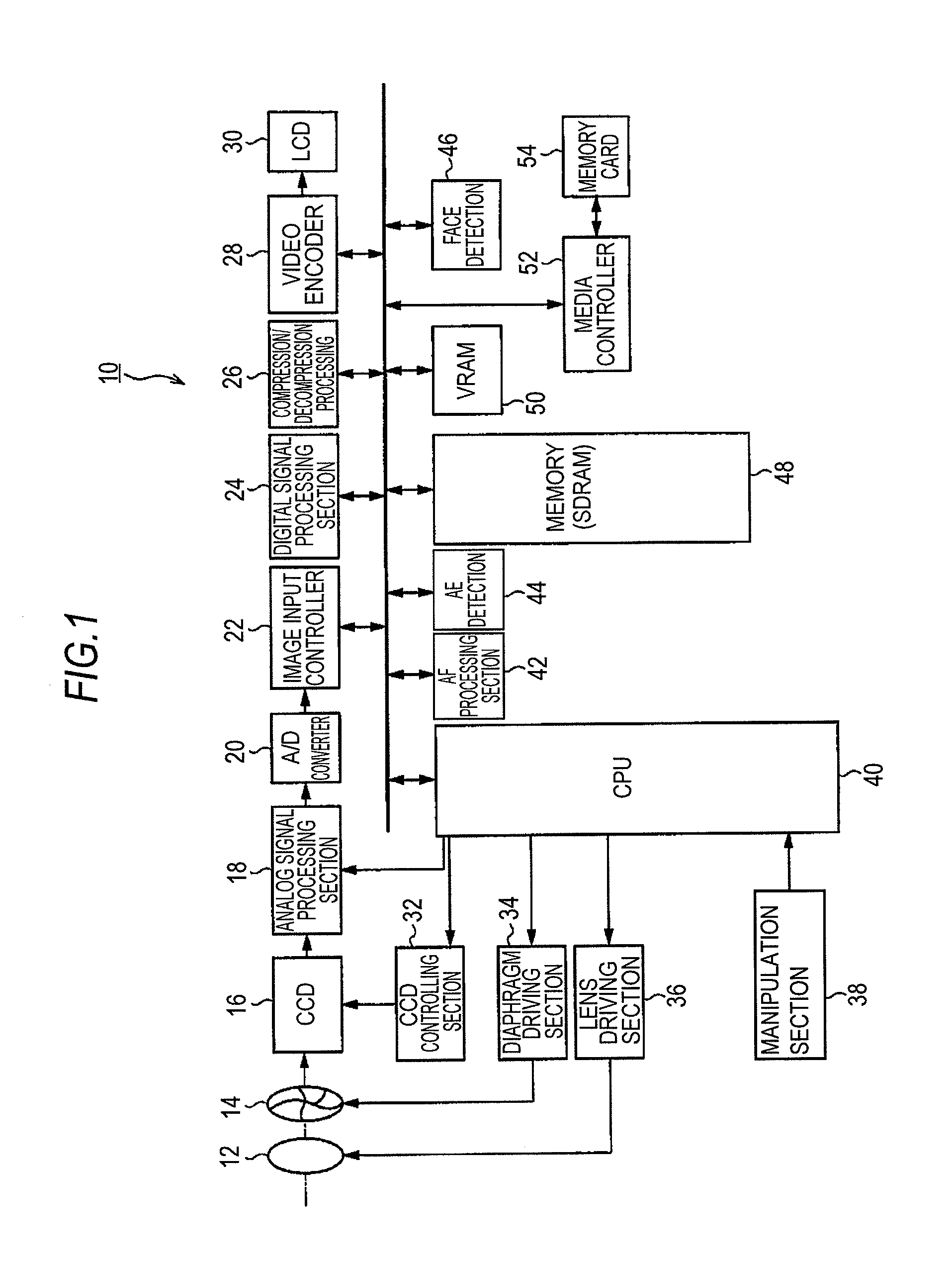
[0090]The stereoscopic imaging apparatus 10 of the first embodiment of the present invention has a function of finding out a focus point of a main object such as a person to perform AF processing. For this kind of function, existing functions can be used. For example, a function in which when a face detection mode is selected, the face of a person in a photographic angle of view is detected by a face detection circuit 46 (FIG. 1), and focus is automatically placed on the face with an area including the face used as an AF area, and a function in which when a line-of-sight input mode is selected, the line of sight of a photographer is detected, whereby a focus point is determined, and focus is placed on the focus point (see JP-H09-101579A (JP1997-101579A) and JP2004-7158A) may be used.

[0091]The stereoscopic imaging apparatus 10 also has a function of designating an arbitrary area within a photographic angle of view as an AF area. For this kind of function, existing functions can be us...

second embodiment

[0103]FIG. 6A is a flowchart of an AF operation in a stereoscopic imaging apparatus 10 of a second embodiment of the present invention.

[0104]When the shutter button is pressed halfway, the CPU 40 starts an AF operation (step S10).

[0105]The CPU 40 determines an AF area when the AF operation starts (step S12). As described above, the AF area is automatically determined or manually set in accordance with the position or the like of a main object within the photographic angle of view.

[0106]Subsequently, it is determined whether the determined AF area belongs to an area (main pixel AF area) where contrast AF is performed using a main pixel image or an area (sub-pixel AF area) where contrast AF is performed using a sub-pixel image (step S14).

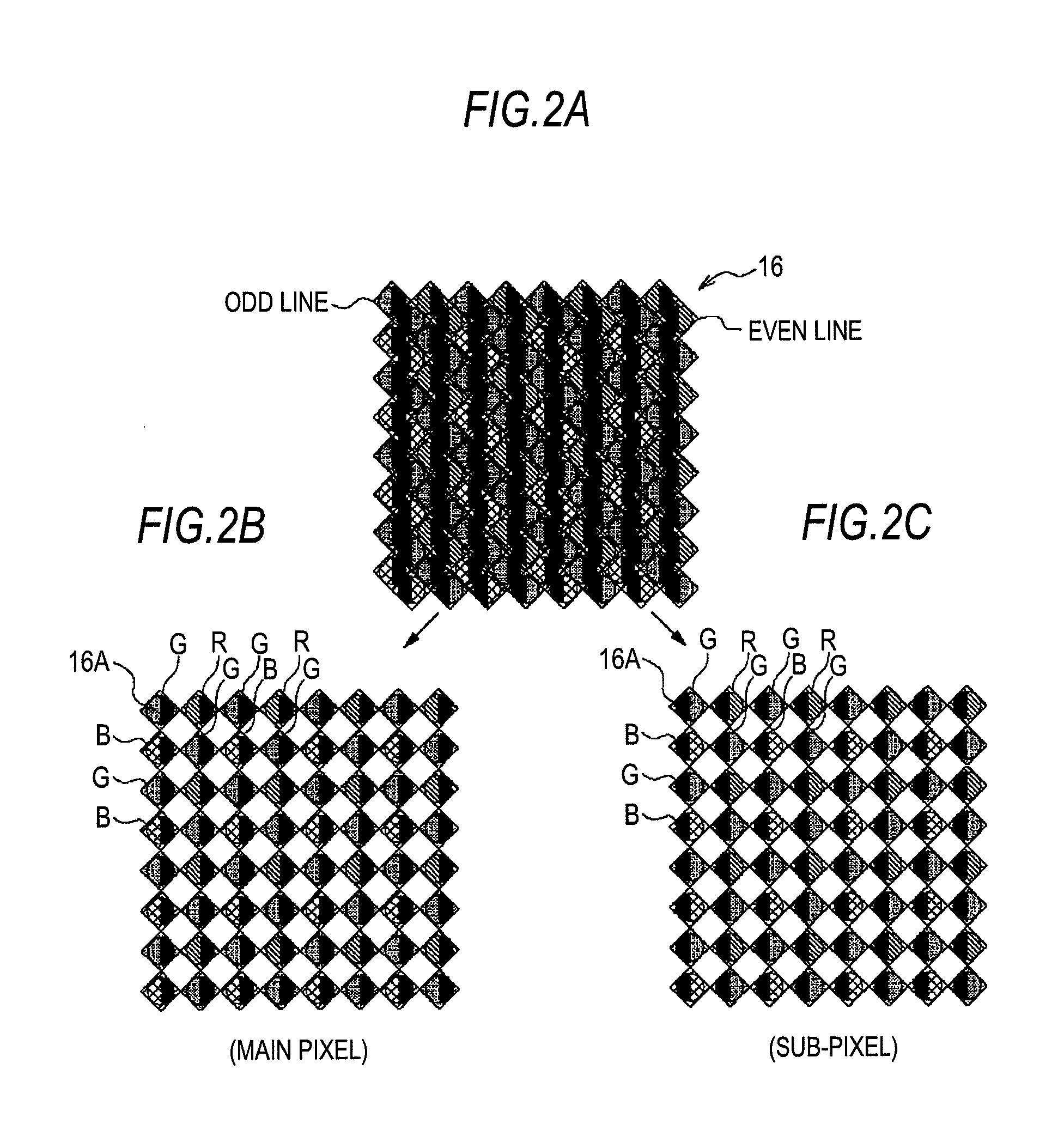
[0107]Here, the main pixel AF area and the sub-pixel AF area are determined in advance as shown in FIG. 6B.

[0108]FIG. 6B shows 80 AF areas which divide a whole phase-difference CCD into 8×10 areas. In the second embodiment, the left half area of FIG. ...

third embodiment

[0116]FIG. 7 is a flowchart of an AF operation in the stereoscopic imaging apparatus 10 of a third embodiment of the present invention. The same steps as the second embodiment shown in FIG. 6A will be denoted by the same step numbers, and detailed description thereof will be omitted.

[0117]As shown in FIG. 7, the third embodiment is different in that the process of step S30 is performed in place of the step S14 shown in FIG. 6A.

[0118]That is, in step S30, the exposure amount of the main pixel and the exposure amount of the sub-pixel in the AF area determined in step S10 are calculated, and an image of a pixel having a larger exposure amount is selected as the image for contrast AF. Therefore, when the exposure amount of the main pixel is larger than the exposure amount of the sub-pixel (“YES”), the flow proceeds to step S16. Conversely, when the exposure amount of the sub-pixel is larger than the exposure amount of the main pixel (“NO”), the flow proceeds to step S26.

[0119]The reason...


PUM


Abstract

A stereoscopic imaging apparatus which uses contrast AF to obviate disadvantages of phase-difference AF, shorten processing time of contrast AF, and improve focusing accuracy. A phase-difference CCD in which object images having passed through different regions in a predetermined direction of a single photographing optical system are pupil-split and imaged subjects the object images having passed through the respective regions to photoelectric conversion to obtain a main pixel image and a sub-pixel image which have a mutual phase difference. Contrast AF is performed using only one of the main pixel image and the sub-pixel image. Which one of the main pixel image and the sub-pixel image will be used for the contrast AF is determined depending on whether the position of an AF area in the angle of view belongs to a main pixel AF area or a sub-pixel AF area.

Description

BACKGROUND OF THE INVENTION[0001]1. Field of the Invention[0002]The present invention relates to a stereoscopic imaging apparatus, and more particularly, to a technique in which object images having passed through different regions in a predetermined direction of a photographing optical system are imaged onto image sensors to obtain a left viewpoint image and a right viewpoint image.[0003]2. Description of the Related Art[0004]Conventionally, a stereoscopic imaging apparatus having an optical system as shown in FIG. 15 is known in the art (see JP2009-527007A).[0005]This optical system has a configuration in which object images having passed through different regions in the horizontal direction of a main lens 1 and a relay lens 2 are pupil-split by a mirror 4 and are imaged onto image sensors 7 and 8 through imaging lenses 5 and 6, respectively.[0006]FIGS. 16A to 16C show separate states of an image imaged onto an image sensor depending on a difference between front-focus, in-focus (...

Claims


Application Information

Patent Timeline
IPC IPC(8): H04N13/02H04N13/239
CPCH04N5/23212H04N13/021H04N13/0203H04N13/0239G02B3/00H04N13/0217H04N13/204H04N13/211H04N13/218H04N13/239H04N23/672H04N23/673H04N25/704H04N25/134
Inventor AOKI, TAKASHI
Owner FUJIFILM CORP
Why Eureka
Try Eureka