Method of Determining the Contact Angle of a Ball Bearing

a technology of contact angle and ball bearing, which is applied in the field of ball bearings, can solve the problems of difficult fitting of the screen, difficult to detect the rotation of the cage, and insufficient precision of the above-mentioned conventional method, and achieve the effect of accurate measurement of the contact angl

Active Publication Date: 2011-09-22
AB SKF
View PDF4 Cites 6 Cited by
  • Summary
  • Abstract
  • Description
  • Claims
  • Application Information

AI Technical Summary

Benefits of technology

[0006]The primary object of the invention is to obtain a very accurate measurement of the contact angle, avoiding the limits of the above d

Problems solved by technology

The abovementioned conventional method is not very precise and has limits of a practical nature.
Specifically, for bearings of very small dimensions in which the space between the inner diameter of the outer ring and the outer diameter of the inner ring is minimal, applying a support on the cage for a screen with opaque sectors in order to detect the rotation of the cage is problematic.
The fitting of the screen is made more difficult if the rings of the bearing are

Method used


Image

  • Method of Determining the Contact Angle of a Ball Bearing
  • Method of Determining the Contact Angle of a Ball Bearing
  • Method of Determining the Contact Angle of a Ball Bearing

Examples


Embodiment Construction

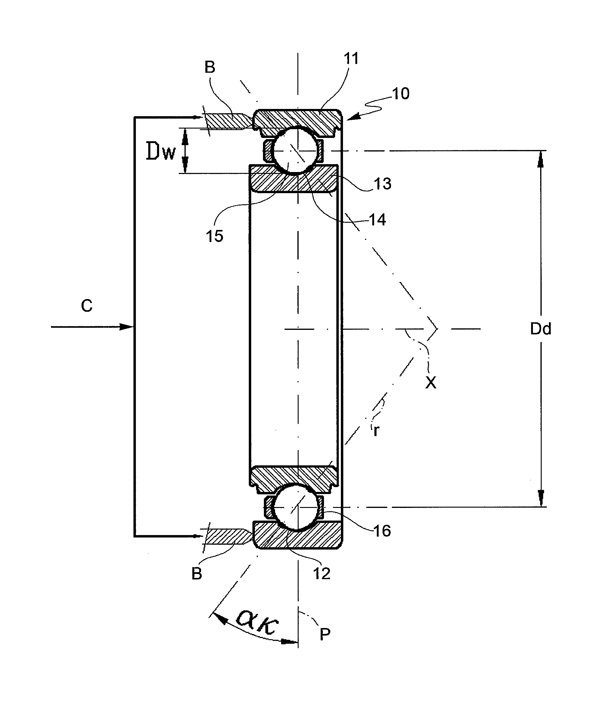
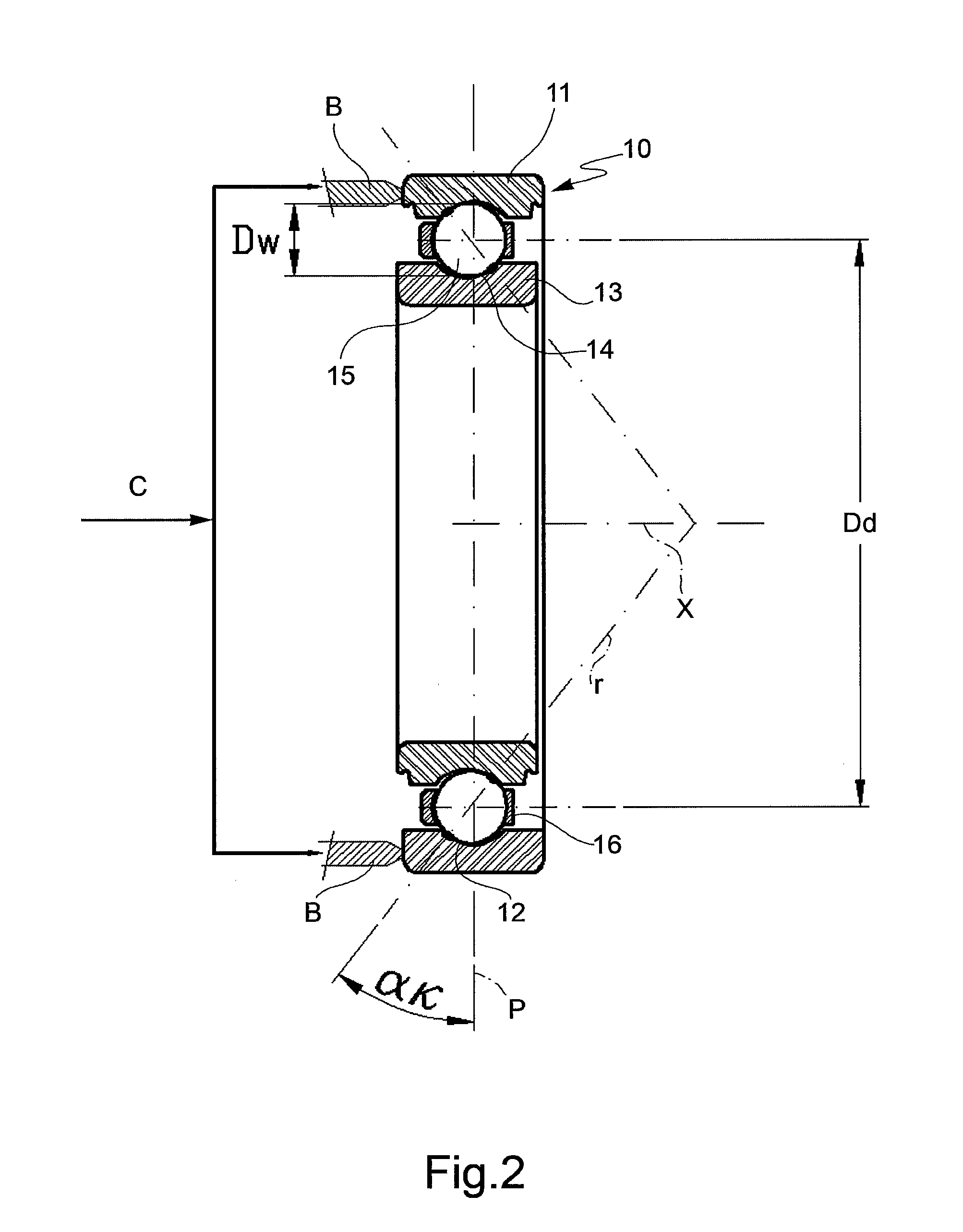
[0013]Referring initially to FIG. 2, designated at 10 in its entirety is a ball bearing for which it is desired to determine the contact angle αk. The bearing 10 has a central axis x and includes an outer ring 11 with an outer raceway 12 on an inner peripheral wall thereof, an inner ring 13 with an inner raceway 14 on an outer peripheral wall thereof, the inner ring 13 being spaced axially from the outer ring 11 so as to define a gap, and a plurality of rolling balls 15. The balls 15 are radially interposed between the outer and inner rings 11, 13, respectively, in order to roll along the outer 12 and inner 14 raceways. The balls 15 are circumferentially spaced from one another by a retaining cage of conventional design 16 disposed generally between the outer and inner rings 11, 13 and each ball 15 has a diameter DW substantially equal to the diameter DW of each other ball 15. In the bearing 10, a line r passing through the points of contact of each ball 15 with the outer raceway 12...


PUM


Abstract

To determine the contact angle of a ball bearing, one of two rings is rotated while the other ring is held stationary. The number of revolutions of the rotated ring and the number of revolutions accomplished in the same period by the balls, and therefore by the retaining cage, are detected. The revolutions of the balls are detected through an optical detecting device which projects a radiation through the bearing, in the gap between the outer and inner rings, whereby the radiation is intercepted directly by the balls and/or the cage. The contact angle is determined using the following parameters: the number of revolutions of the rotating ring, the number of revolutions of the balls or of the cage, the diameter of the balls, and the pitch diameter.

Description

CROSS-REFERENCE[0001]This application claims priority to Italian Patent Application No. TO2010A000197 filed on Mar. 16, 2010, the contents of which are incorporated fully herein by reference.BACKGROUND OF THE INVENTION[0002]The present invention relates to bearings, and more particularly to a method of determining the contact angle of a ball bearing.[0003]U.S. Pat. No. 5,423,218-A discloses a method for measuring the contact angle based on the detection of radial vibrations, by means of a pickup sensor applied on the outer ring of the bearing. The inner ring of the bearing is rotated while the outer ring is held stationary and subjected to an axial load. The signal detected by the pickup is transmitted to a frequency converter through an amplifier. The frequency converter determines, by calculation, the frequency of rotation of the inner ring and the frequency of the number of passes of the balls, and from the computation of these frequencies, it calculates the contact angle.[0004]A...

Claims


Application Information

Patent Timeline
IPC IPC(8): G01B11/26
CPCG01B11/26G01P3/486G01M13/04
Inventor ARCIULI, VITO
Owner AB SKF
Why Eureka
Try Eureka