Developing device and image forming apparatus including the same

a technology of developing device and image forming apparatus, which is applied in the direction of electrographic process apparatus, instruments, optics, etc., can solve the problems of easy malfunction, complex apparatus structure of developing device, and prone to positive pressure inside the developing device, so as to achieve the effect of preventing the deposition of toner

Inactive Publication Date: 2011-09-22
KYOCERA DOCUMENT SOLUTIONS INC
View PDF10 Cites 28 Cited by
  • Summary
  • Abstract
  • Description
  • Claims
  • Application Information

AI Technical Summary

Benefits of technology

[0021]It is an object of the present invention to provide a developing device capable of effectively preventing deposition of toner in a casing, and to provide an image forming apparatus including the developing device.

Problems solved by technology

By the way, in recent years, in the image forming apparatus, an apparatus structure thereof has become complicated as color printing has been increased and a processing speed has been enhanced, and in addition, high speed rotation of a toner stirring member in a developing device has been forced in order to cope with such enhancement of the processing speed.
In this case, a pressure inside the developing device is prone to be a positive pressure higher than the atmospheric pressure.
As a result, such a malfunction becomes prone to occur, that there occurs a so-called toner lack phenomenon in which the toner is not supplied to a portion on the circumferential surface of the photosensitive drum, on which the toner should be stacked.
Therefore, in many cases, strength of an airflow attempting to go toward the vent hole is not so strong as to cancel a flow of air attempting to accompany the rotation of the developing roller.
As a result, there is a problem in that the air containing the floating toner becomes prone to flow toward the circumferential surface of the photosensitive drum by the rotation of the developing roller, resulting in leakage of the air concerned from a toner supply opening of the casing opposed to the same circumferential surface.
In the case where the deposited toner is aggregated and adhered onto the developing roller, there is also an apprehension that such a toner lack may occur to cause a malfunction of the image.
However, even in the case where the air inflow ports are provided as described above, in the case where the processing speed of the apparatus main unit is enhanced, and a floating amount of the toner is large, it becomes difficult to sufficiently bear the floating toner on the airflow generated by the rotation of the magnetic roller and the developing roller, and it becomes difficult to sufficiently prevent the deposition of the toner.

Method used


Image

  • Developing device and image forming apparatus including the same
  • Developing device and image forming apparatus including the same
  • Developing device and image forming apparatus including the same

Examples


first embodiment

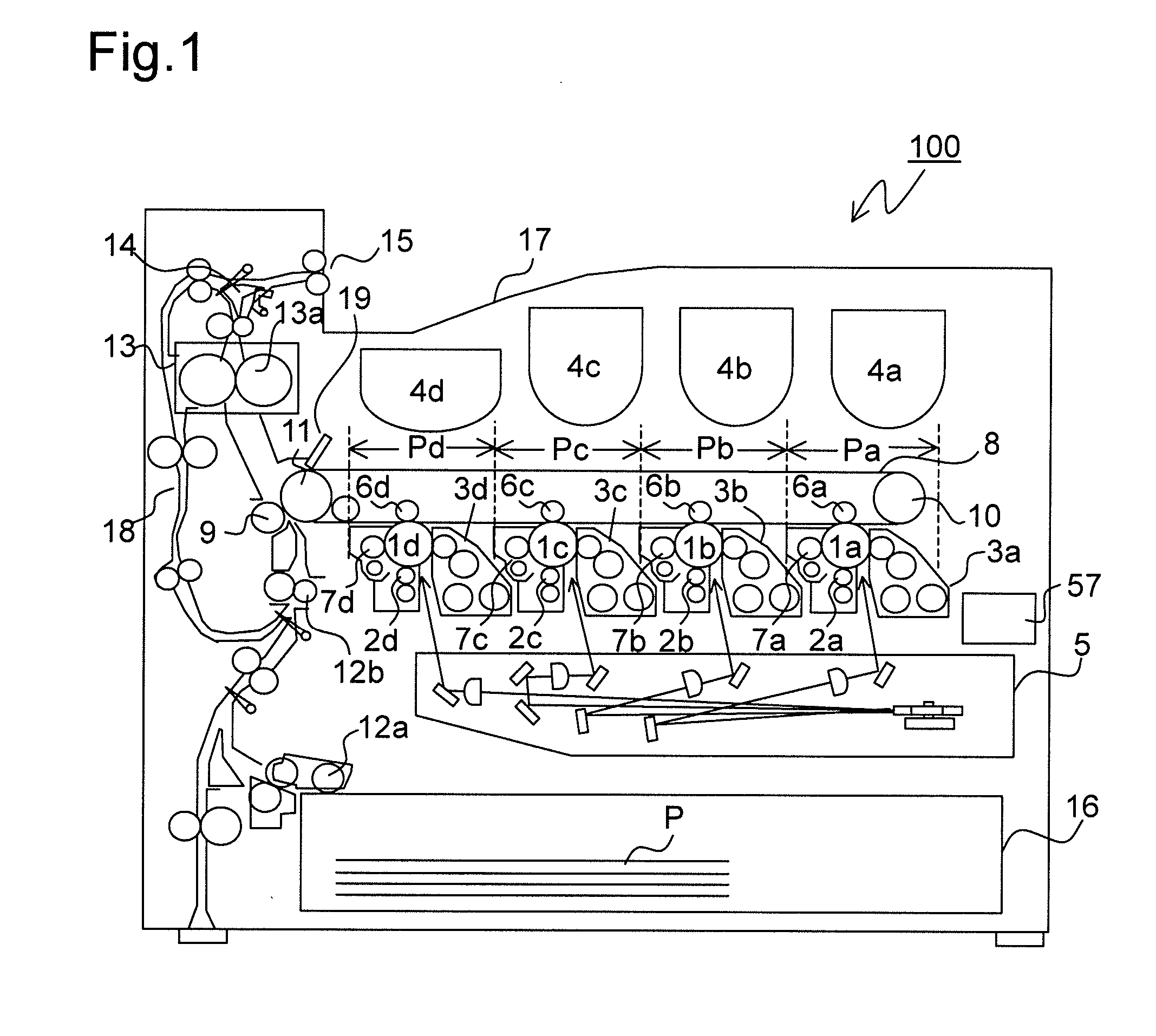
[0072]FIG. 2 is a schematic sectional side view of a developing device according to the present invention. Note that, FIG. 2 indicates a state viewed from a back surface side of FIG. 1, and the respective members within the developing device are arranged so as to be horizontally reverse to FIG. 1. Further, the description here is directed to the developing device 3a located in the image forming portion Pa of FIG. 1, but the developing devices 3b to 3d located in the image forming portions Pb to Pd, respectively, basically have the same structure as the developing device 3a, and hence description thereof is omitted.

[0073]As illustrated in FIG. 2, the developing device 3a includes a developing container (casing) 20 for storing a two-component developer (hereinafter, referred to simply as “developer”), and the developing container 20 is partitioned by partition walls 20a and 20b into a stirring-transport chamber 21, a supplying-transport chamber 22, and a collecting-transport chamber 2...

third embodiment

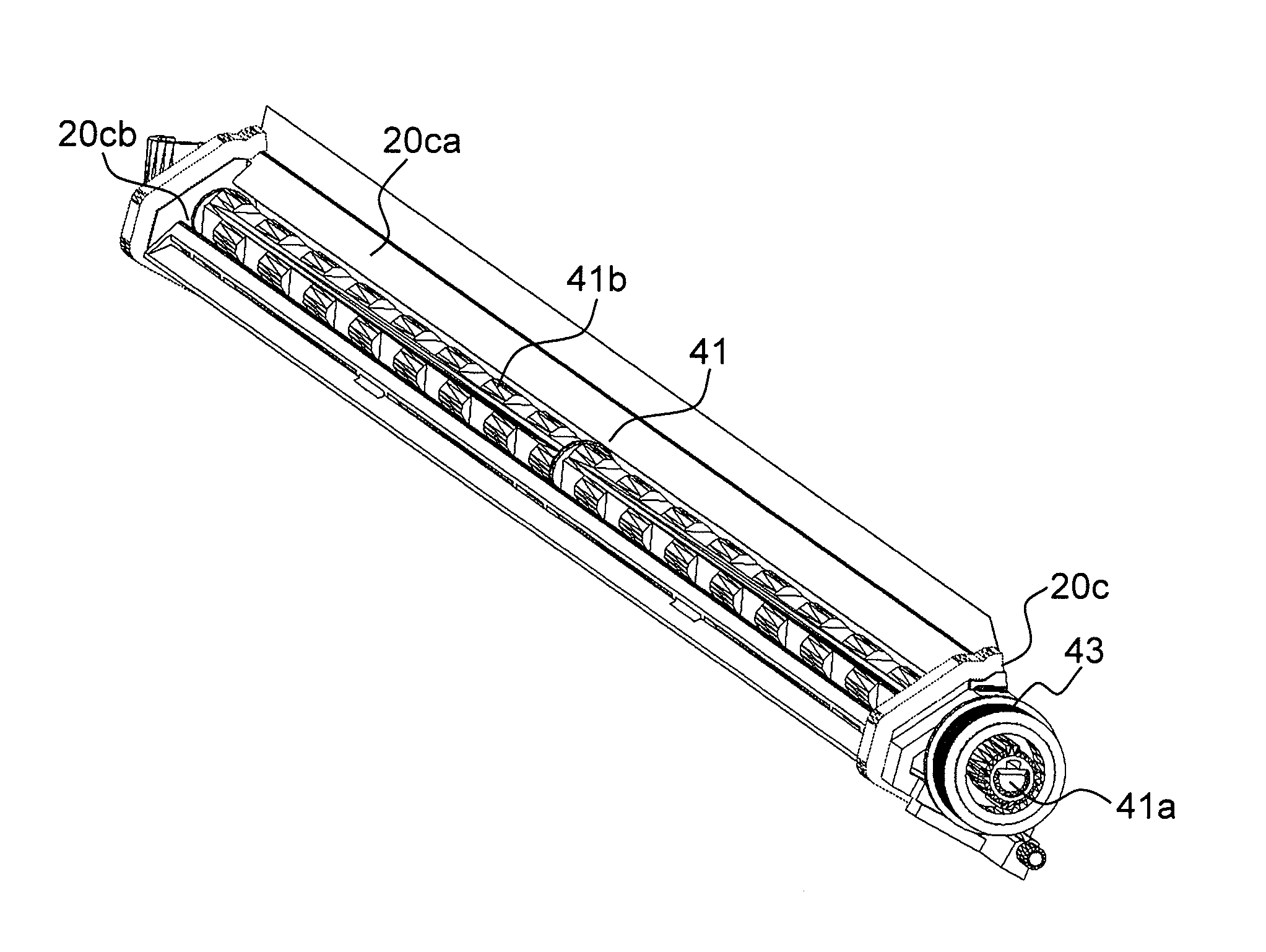
[0104]FIG. 9 is a schematic sectional side view illustrating peripheries of a sheet member and an oval roller, which are used in a developing device according to the present invention, and FIG. 10 is a schematic sectional side view illustrating a state in which notched portions of the oval roller scrape out the toner in the recessed portion. Reference symbols common to those in FIG. 7 are assigned to portions common to those therein, and a description of the common portions is omitted.

[0105]In this embodiment, on the circumferential surface of the oval roller 41, notched portions 41c are formed, which are capable of scraping out the toner that has entered the recessed portion 20cb. In such a way, the cross section of the oval roller 41 is formed of two substantial sectors arranged at positions point symmetric to each other with respect to the rotation shaft 41a as a center. Other structures are similar to those of the first embodiment, and accordingly, a description thereof is omitt...


PUM


Abstract

A developing device includes: a developer carrying member for supplying a developer to an image bearing member at an opposing region opposing to the image bearing member, the developer carrying member being arranged so as to be opposed to the image bearing member on which an electrostatic latent image is to be formed; a blade for regulating an amount of the developer carried on the developer carrying member; a casing for housing the developer carrying member and the blade, the casing including a wall portion opposed to the developer carrying member between the blade and the opposing region; a sheet member that is flexible, provided on the wall portion, has a free end, forms a part of an inner wall surface of the wall portion, and is movable in a direction perpendicular to the inner wall surface; and a moving portion provided on the wall portion, for moving the sheet member.

Description

[0001]This application is based upon and claims the benefit of priority from the corresponding Japanese Patent Application No. 2010-62914 filed on Mar. 18, 2010 and Japanese Patent Application No. 2010-63013 filed on Mar. 18, 2010, the entire contents of which are incorporated herein by reference.BACKGROUND OF THE INVENTION[0002]1. Field of the Invention[0003]The present invention relates to an electrophotographic image forming apparatus including an image bearing member and a developing device.[0004]2. Description of Related Art[0005]An electrophotographic image forming apparatus irradiates a circumferential surface of an image bearing member (photosensitive drum) with light based on image information which is obtained by reading an image of a document and transmitted from an external instrument such as a computer. Accordingly, the electrophotographic image forming apparatus forms an electrostatic latent image, supplies the electrostatic latent image with toner to form a toner imag...

Claims


Application Information

Patent Timeline
Patent Type & Authority Applications(United States)
IPC IPC(8): G03G21/20
CPCG03G15/0896
Inventor KASHIMOTO, MASAHIRONISHIMURA, RYOJIOHASHI, HIROAKI
Owner KYOCERA DOCUMENT SOLUTIONS INC
Why Eureka
Try Eureka