Buried etch stop layer in trench isolation structures for superior surface planarity in densely packed semiconductor devices

Inactive Publication Date: 2011-03-03
ALSEPHINA INNOVATIONS INC
View PDF3 Cites 23 Cited by
  • Summary
  • Abstract
  • Description
  • Claims
  • Application Information

AI Technical Summary

Benefits of technology

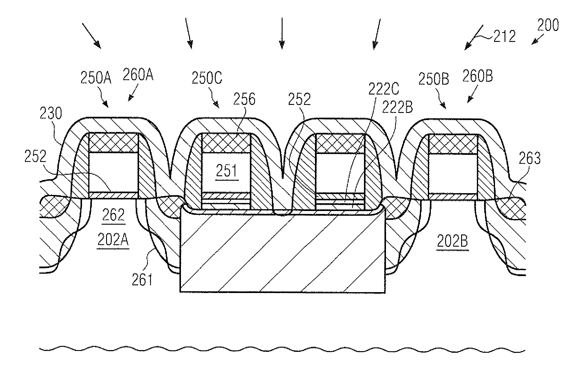
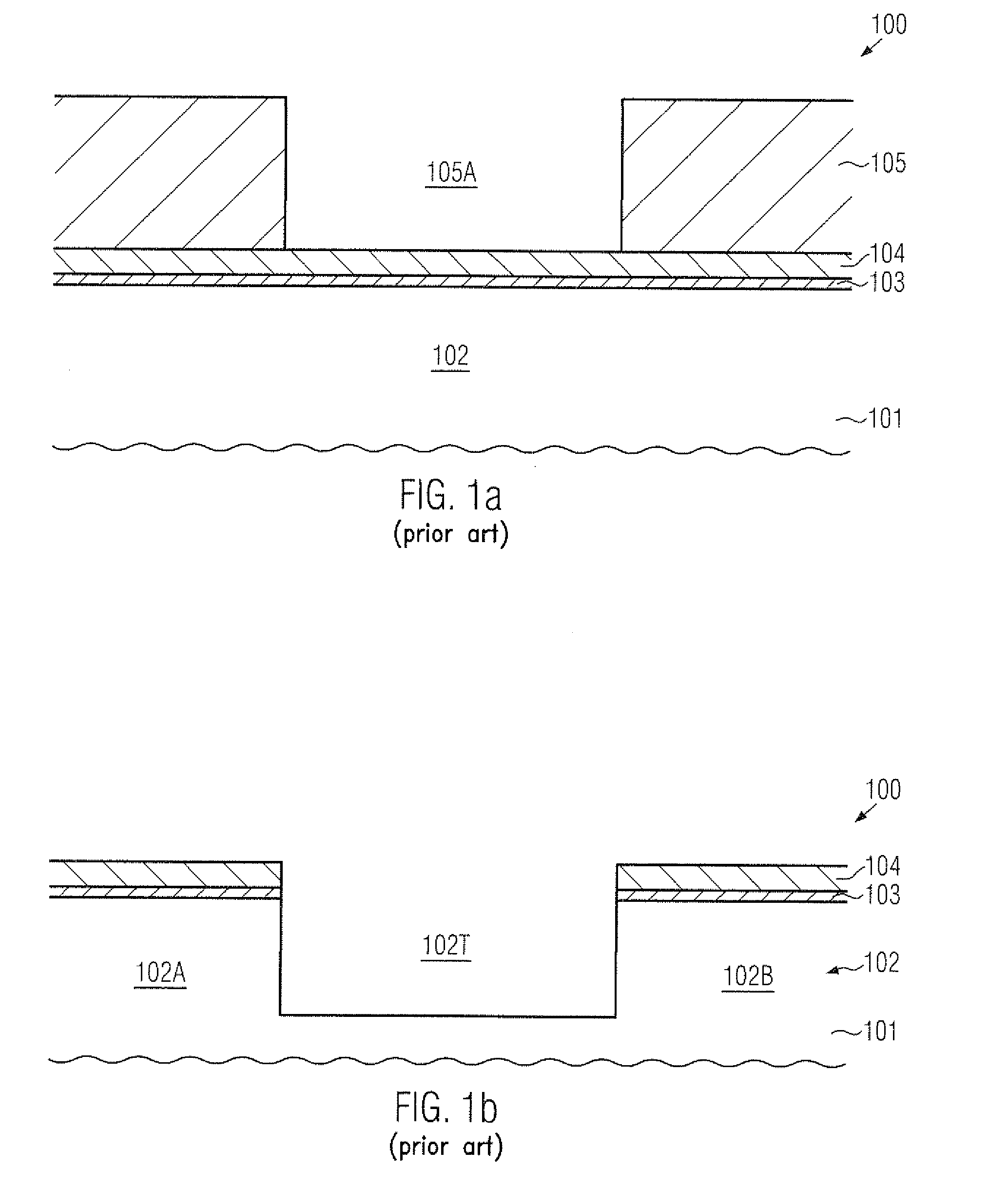
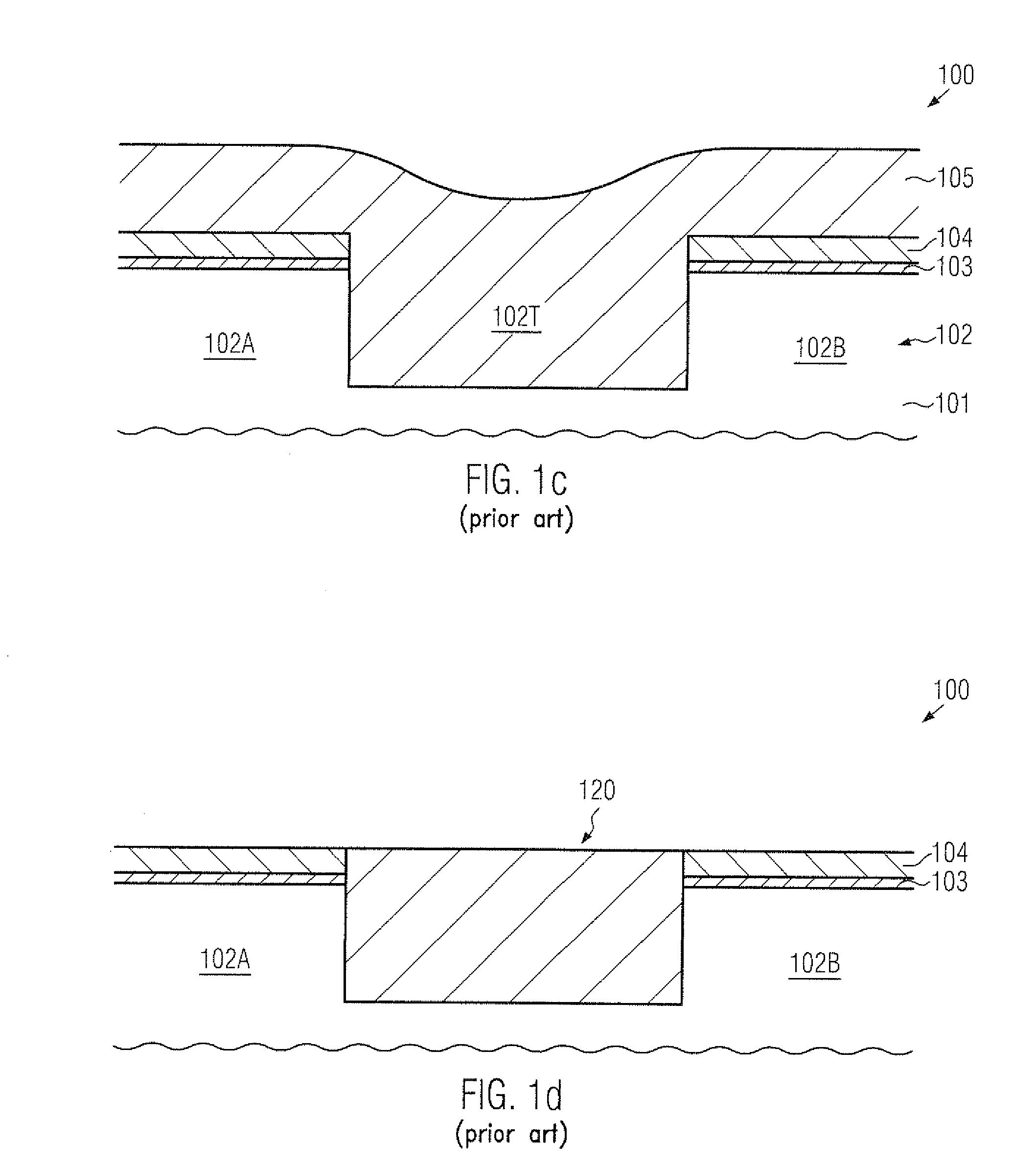
[0030]One illustrative method disclosed herein comprises forming an etch stop layer on a trench isolation structure that laterally delineates an active region in a semiconductor layer of a semiconductor device. The method further comprises forming a first gate electrode structure on the active region and performing a cleaning process on the active region while using the etch stop layer so as to suppress material erosion of the trench isolation structure. The method further comprises forming a dielectric layer of an interlayer dielectric material above the active region, the gate electrode structure and the trench isolation stru

Problems solved by technology

On the other hand, the continuous shrinkage of the gate length of planar transistor configurations may typically result in very sophisticated topographical configurations since the gate height may not be proportionally reduced in relation to the gate length unless very complicated process strategies are used for maintaining the desired overall gate conductivity and the ion blocking effect during the formation of drain and source regions of the transistors in which the gate electrode, in combination with a spacer structure, typically acts as an implantation mask.
As is well known, after performing etch processes based on an etch mask and a complex etch chemistry, typically, significant contamination of the

Method used


Image

  • Buried etch stop layer in trench isolation structures for superior surface planarity in densely packed semiconductor devices
  • Buried etch stop layer in trench isolation structures for superior surface planarity in densely packed semiconductor devices
  • Buried etch stop layer in trench isolation structures for superior surface planarity in densely packed semiconductor devices

Examples


Example

[0035]While the subject matter disclosed herein is susceptible to various modifications and alternative forms, specific embodiments thereof have been shown by way of example in the drawings and are herein described in detail. It should be understood, however, that the description herein of specific embodiments is not intended to limit the invention to the particular forms disclosed, but on the contrary, the intention is to cover all modifications, equivalents, and alternatives falling within the spirit and scope of the invention as defined by the appended claims.

DETAILED DESCRIPTION

[0036]Various illustrative embodiments of the invention are described below. In the interest of clarity, not all features of an actual implementation are described in this specification. It will of course be appreciated that in the development of any such actual embodiment, numerous implementation-specific decisions must be made to achieve the developers' specific goals, such as compliance with system-rel...


PUM


Abstract

Material erosion of trench isolation structures in advanced semiconductor devices may be reduced by incorporating an appropriate mask layer stack in an early manufacturing stage. For example, a silicon nitride material may be incorporated as a buried etch stop layer prior to a sequence for patterning active regions and forming a strain-inducing semiconductor alloy therein, wherein, in particular, the corresponding cleaning process prior to the selective epitaxial growth process has been identified as a major source for causing deposition-related irregularities upon depositing the interlayer dielectric material.

Description

BACKGROUND OF THE INVENTION[0001]1. Field of the Invention[0002]Generally, the present disclosure relates to the field of integrated circuits, and, more particularly, to circuit elements, such as field effect transistors, and manufacturing techniques in which sophisticated surface topographies lead to deposition-related yield losses in the contact level of semiconductor devices.[0003]2. Description of the Related Art[0004]Integrated circuits typically include a large number of circuit elements located on a given chip area according to a specified circuit layout, wherein, in complex circuits, the field effect transistor represents one predominant circuit element. Generally, a plurality of process technologies for advanced semiconductor devices are currently practiced, wherein, for complex circuitry based on field effect transistors, such as microprocessors, storage chips, graphic devices and the like, MOS technology is currently one of the most promising approaches due to the superio...

Claims


Application Information

Patent Timeline
IPC IPC(8): H01L27/088H01L21/8234
CPCH01L21/28123H01L21/76224H01L29/165H01L29/7848H01L29/66636H01L29/7834H01L29/665
Inventor WIATR, MACIEJFORSBERG, MARKUSKRONHOLZ, STEPHANBOSCHKE, ROMAN
Owner ALSEPHINA INNOVATIONS INC
Why Eureka
Try Eureka