
Apparatus and method for phase-space reduction for imaging of fluorescing, scattering and/or absorbing structures

a technology of phase space and fluorescence, applied in the field of apparatus and phasespace reduction for imaging of fluorescing scattering and/or absorbing structures, can solve the problems of somewhat degraded alternative performance yet useable performance, and achieve the effect of preferential absorption of energy, higher vascularization, and absorbing energy

Inactive Publication Date: 2012-03-08
LIFAN WANG +4
View PDF9 Cites 22 Cited by
  • Summary
  • Abstract
  • Description
  • Claims
  • Application Information

AI Technical Summary

Benefits of technology

The present invention is about a method and apparatus for using non-hazardous sources of illumination to detect and differentiate objects using ultraviolet, optical, and infrared light. The device can detect different objects, such as tumors, cancer, Traumatic Brain Injury (TBI), blood clots, and blood flow, with depth penetration of at least one centimeter. The device is safe, easy to use, and ubiquitous, making it useful in various settings such as a family practice office or a battlefield hospital. The technique uses collimators to focus and analyze the reflected, scattered, absorbed, or transmitted light. The apparatus can also be used with transmitted light, absorbed light, scattered or reflected light, or a combination of these. The device can provide valuable information about the underlying structures and functions of biological, organic, and non-biological materials.

Problems solved by technology

Such alternatives may have somewhat degraded but yet useable performance, than when the detecting collimator is located at the distal end.

Method used


Image

  • Apparatus and method for phase-space reduction for imaging of fluorescing, scattering and/or absorbing structures
  • Apparatus and method for phase-space reduction for imaging of fluorescing, scattering and/or absorbing structures
  • Apparatus and method for phase-space reduction for imaging of fluorescing, scattering and/or absorbing structures

Examples


Embodiment Construction

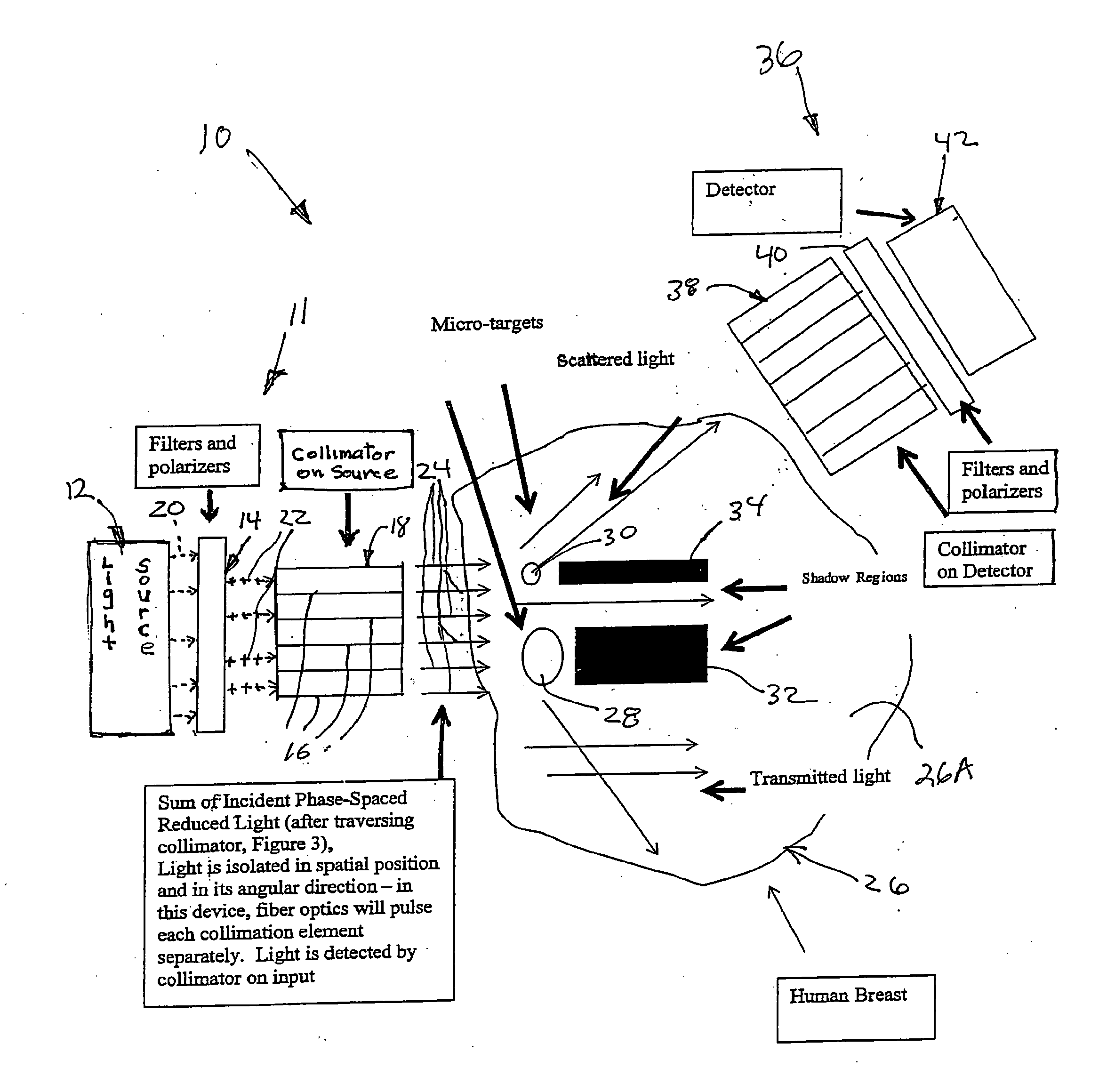
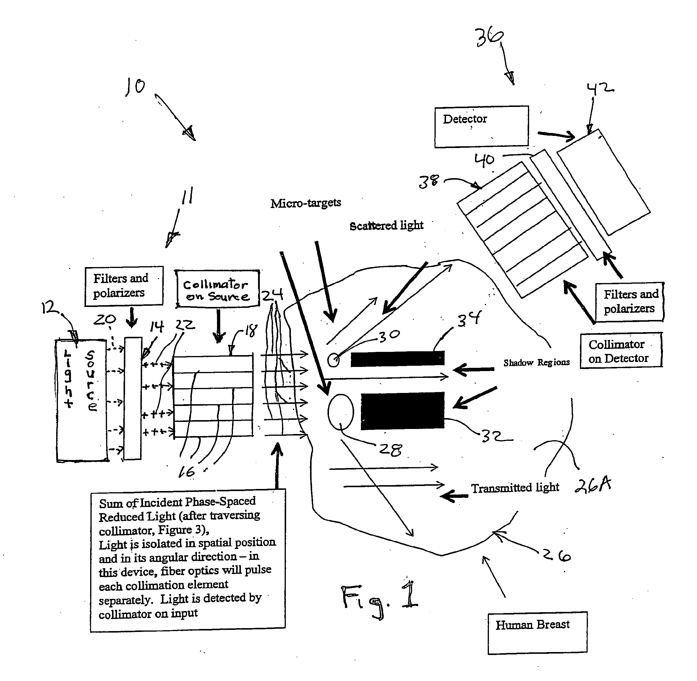
[0034]Referring to FIG. 1, a first embodiment of apparatus 10 of and for practicing the present invention is shown. Starting from the left, it includes or comprises an input or illuminator unit 11, light source 12, optionally filters and / or polarizers 14, preferably, and a plurality of collimator tubes 16 forming an input collimator 18. The light source could be photo diodes, diode lasers, or incandescent or other lighting, with or without filters, with the purpose of injecting light into the subject with phase-space reduced beams. As shown by the dotted arrows 20, light leaves the light source 12 and enters and is altered in the filters / polarizers 14. Light from the filters / polarizers 14, if used, or from the light source 12, if filters / polarizers are not used, then enters collimator 18 and collimator tubes 16, as indicated by the plus arrows 22. From there collimated or collinear light 24 strikes the target 26, in this instances a human breast.

[0035]The collinear light 24, is to s...


PUM

PropertyMeasurementUnit
temperatureaaaaaaaaaa
depthaaaaaaaaaa
depthaaaaaaaaaa

Abstract

A method and apparatus are disclosed for utilizing light, including ultraviolet, optical and / or infrared, for detecting a body in an object, such as biomaterial or tissue, animal and / or human tissue. The body or object may be made fluorescent by the use of dyes or agent. Light is used to illuminate the body and object and the scattered light, fluorescent and / or emitted light, reflected light and transmitted light are detected and used to reconstruct the body and / or object using an iterative analysis. Further, the method and apparatus may be extended to endoscopic applications to make subcutaneous images of internal tissue above, on, in or beyond endoscopic pathways such as esophagus, stomach, colon, bronchial tubes and / or other openings, cavities and spaces animate or inanimate, and in man-made or industrial materials as carbon / resin structures.

Description

CROSS-REFERENCE TO RELATED APPLICATIONS[0001]This is a United States Patent Cooperation Treaty (PCT) Patent Application which is a continuation-in-part of and claims priority and the filing dates of Provisional Application No. 60 / 918,006, filed Mar. 14, 2007, entitled “Apparatus and Method for Phase-Space Reduction for Measuring Sub-Surface Scattering and Absorption Centers”, in the names of inventors: Lifan Wang, Carl Pennypacker, William Sheehan, James W. Gee, Jr., and Michael Piontek and Provisional application Ser. No. ______, filed Mar. 4, 2008, entitled “Apparatus and Method for Phase-Space Reduction for Imaging of Fluorescing, Scattering and / or Absorbing Structures”, in the names of inventors: Lifan Wang, Carl Pennypacker, William Sheehan, James W. Gee, Jr., and Michael Piontek, both of which are herein incorporated by reference, and relate to a method and apparatus for phase-space reduction and measuring sub-surface scattering and absorption centers using ultraviolet, optica...

Claims


Application Information

Patent Timeline
Patent Type & Authority Applications(United States)
IPC IPC(8): A61B6/00A61B1/06G01N21/64A61B18/18G01N21/27G01J3/00
CPCA61B1/043A61B5/0071A61B5/0084G01J3/0208G01J3/0218G01J3/0224A61B1/07G01J3/0262G01J3/44G01N21/4795G01N21/6456A61B1/00186A61B1/0646G01J3/0229
Inventor LIFAN, WANGPENNYPACKER, CARL R.SHEEHAN, WILLIAMGEE, JR., JAMES W.PIONTEK, MICHAEL
Owner LIFAN WANG
Learn More