
Transport management system

Inactive Publication Date: 2011-09-22
AVEGO LTD
View PDF10 Cites 47 Cited by
  • Summary
  • Abstract
  • Description
  • Claims
  • Application Information

AI Technical Summary

Benefits of technology

[0043]relative link performance rating live feed

Problems solved by technology

A problem with existing car sharing urban transport systems is that of providing up-to-date location and route information.
Typically, this involves costly frequent mobile network transmissions.
It is not sufficient to merely ask the driver at the start of their journey which route they intend to take, since driving conditions are dynamic.
Their destination might change, they may deviate from the route momentarily, or their progress along the route may change unexpectedly, due to traffic conditions and the driver's free will.
If the devices do not submit regular update information, the server's understanding of vehicles on the ground will fall out of date.
This would take too much time to provide a practical service to the traveller.
Utilising costly cellular communication resources (such as GPRS) for regular updates increases the overall cost of operating these services to a point where it compares unfavourably with the actual cost of the transport service itself.
Adoption of such location-based services has therefore until now been limited.
Additionally, it is not practical to assume that cellular communication coverage is available all of the time, and hence a method is needed to allow services to be provided when cellular communication coverage is available only intermittently.

Method used


Image

  • Transport management system
  • Transport management system
  • Transport management system

Examples


Embodiment Construction

System Overview

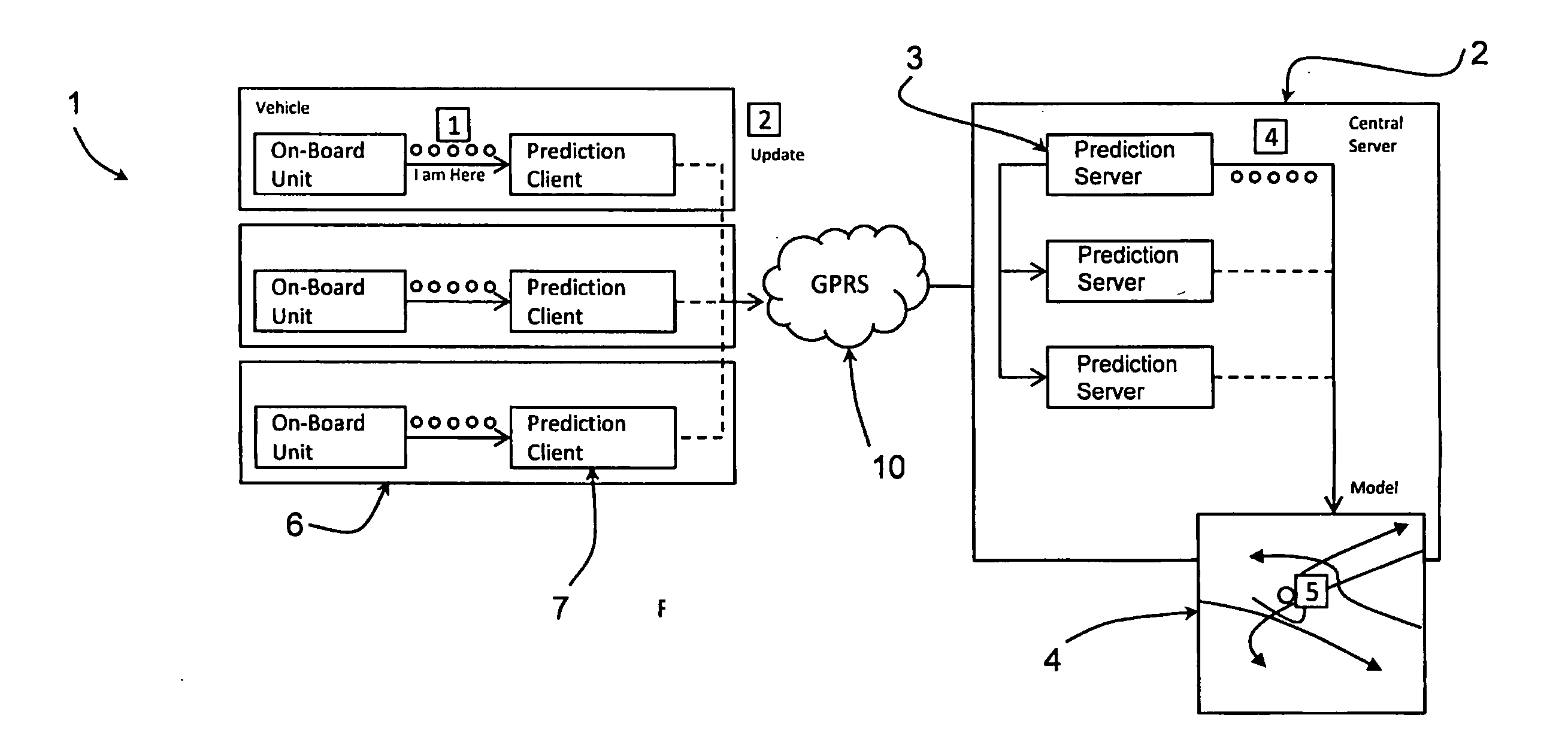
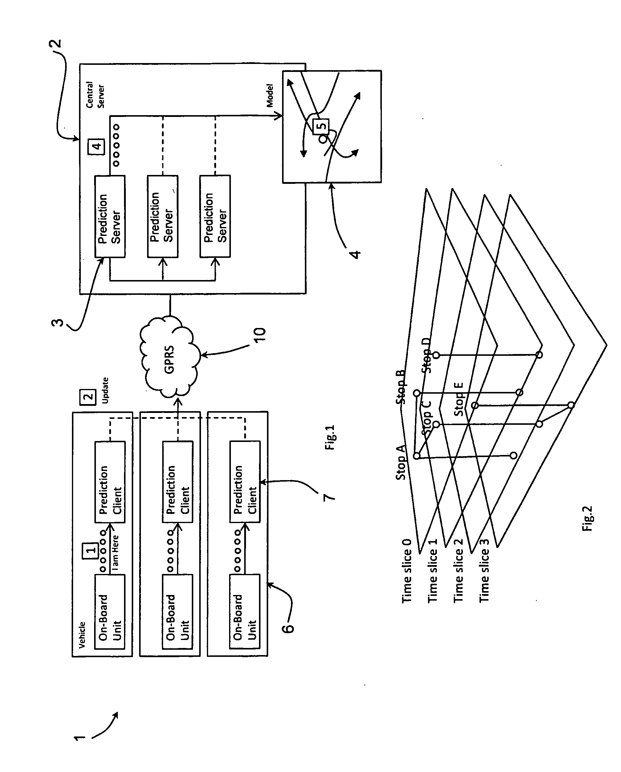
[0052]Referring to FIG. 1 a car pooling transport management system 1 comprises a central server 2 having a bank of prediction servers 3 linked with a geographical model 4. Vehicle on-board units (“OBUs”) 6 have prediction clients 7 which communicate with the central server 2 via a mobile network 10. Each OBU 6 has a satellite locating system, in this case GPS-based, to track actual vehicle position. The hardware for the OBU is available as is known by those skilled in the art, the invention residing in the manner in which the OBUs 6 and the servers 3 are programmed.

[0053]Each prediction client 7 serves two purposes:[0054](a) in a data gathering and modelling mode, to locally, on the vehicle, develop a vehicle prediction model for the driver's regular routes, and to communicate data concerning the vehicle prediction model to a prediction server 3 running on the central server 2, and[0055](b) in a normal transport / commuting mode, to compare in real time the position an...


PUM


Abstract

A car pooling transport management system (1) comprises a central server (2) having a bank of prediction servers (3) linked with a geographical model (4). Vehicle on-board units (OBUs, 6) have prediction clients (7) which communicate with the central server (2) via a mobile network (10). Each OBU (6) has a satellite locating system, in this case GPS-based, to track actual vehicle position. Each prediction client 7 develops a vehicle prediction model for the driver's regular routes and communicates data concerning the vehicle prediction model to a prediction server (3) running on the central server (2), and in a normal transport / commuting mode compares in real time the position and timing of the actual mute of the vehicle against a route of the vehicle prediction model and transmits progress updates to the prediction server (3). The prediction server 3 consolidates the data from the various prediction clients 7 and builds a geographical model 4 for all of the OBUs 6 of the system 1. Using the geographical model (4), the prediction server (3) can continue to provide predictions of the vehicle's progress, such that passenger requests can be processed without using the costly communication resource. Only when the prediction client (7) decides that vehicle progress has materially deviated from its predicted route, by comparing actual progress from say GPS with the local client prediction, does it communicate with the server 3.

Description

FIELD OF THE INVENTION[0001]The invention relates to a transport system for managing utilisation of shared vehicles.PRIOR ART DISCUSSION[0002]U.S. Pat. No. 6,697,730 (Georgia Tech) describes an urban transit system employing cellular communication, GPS locating technology, and computers to provide real time command and control of passengers and vehicles.[0003]JP2004220396 describes a car sharing information supply system.[0004]US2003182183 describes a method of organising a multi car pool.[0005]U.S. Pat. No. 7,136,747 describes a method of GPS rendezvous tracking and personal safety verification[0006]A problem with existing car sharing urban transport systems is that of providing up-to-date location and route information. Typically, this involves costly frequent mobile network transmissions.[0007]It should be noted that in such systems a server must know the intended route of each vehicle in order to know which subset of vehicles should be offered a job. It is not sufficient to mere...

Claims


Application Information

Patent Timeline
IPC IPC(8): G06N5/02
CPCG08G1/20G08G1/0104
Inventor O'SULLIVAN, SEANAPPELBE, HARVEYBALMER, GREG
Owner AVEGO LTD
Learn More