Communication network management system, method and program, and management computer

Inactive Publication Date: 2011-09-22
NEC CORP
View PDF19 Cites 26 Cited by
  • Summary
  • Abstract
  • Description
  • Claims
  • Application Information

AI Technical Summary

Benefits of technology

[0024]According to the present invention, it is possible to reduce burden placed on each node, when performing

Problems solved by technology

However, if communication between a node and the next node is not available, the traveling of the health-check packet is not achieved and thus the monitoring terminal cannot receive the health-che

Method used


Image

  • Communication network management system, method and program, and management computer
  • Communication network management system, method and program, and management computer
  • Communication network management system, method and program, and management computer

Examples


Example

1. First Exemplary Embodiment

[0078]1-1. Configuration

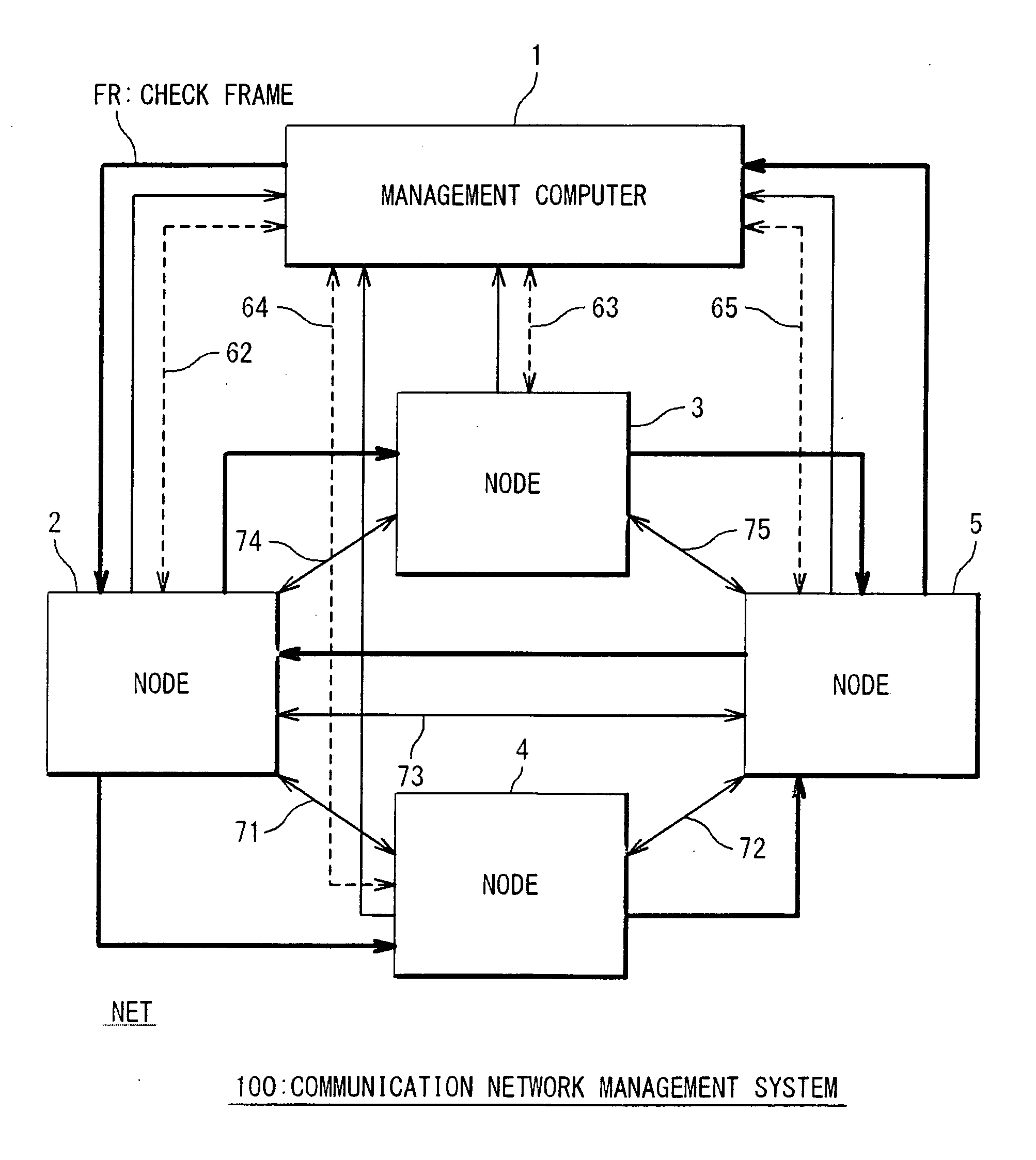
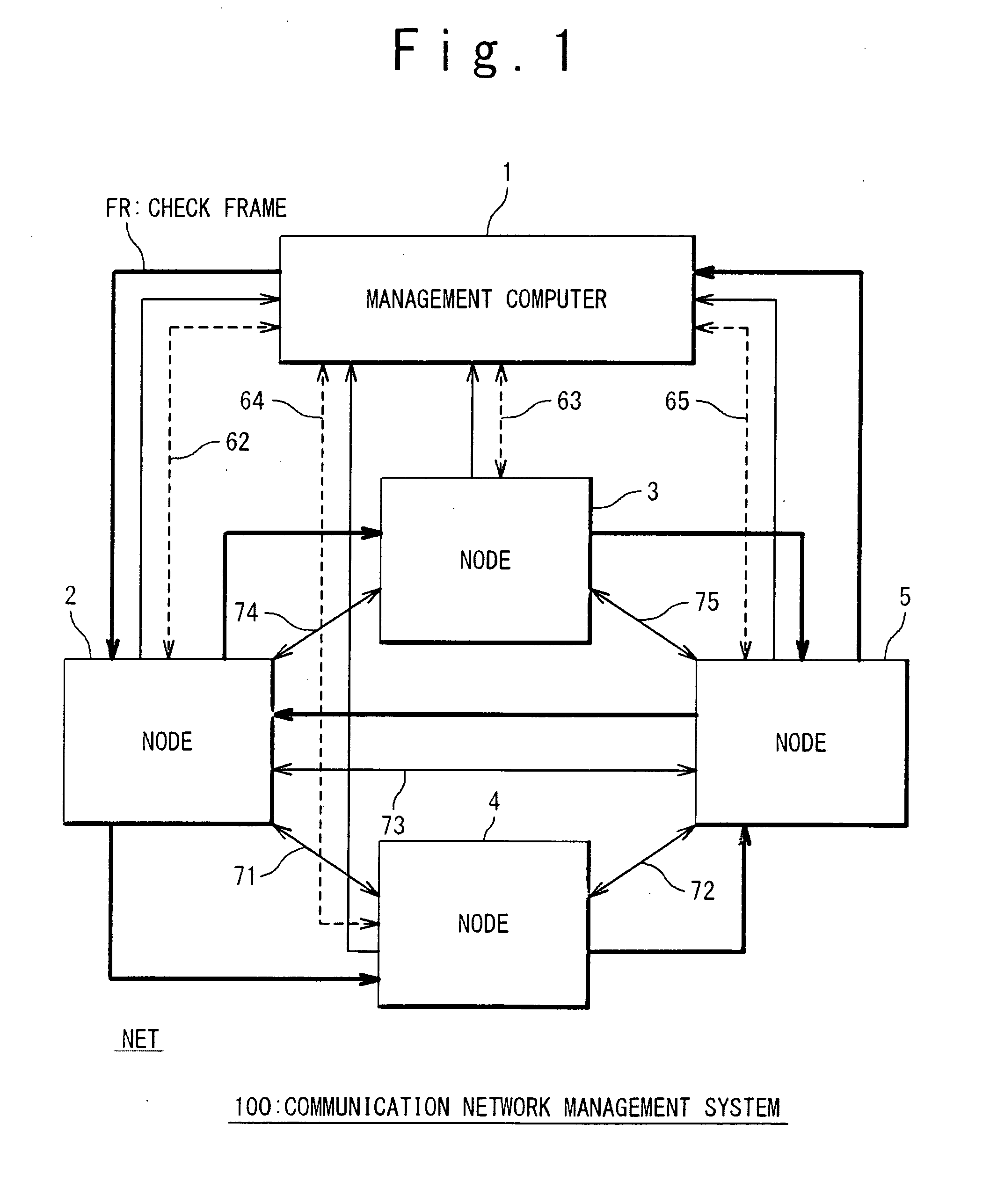
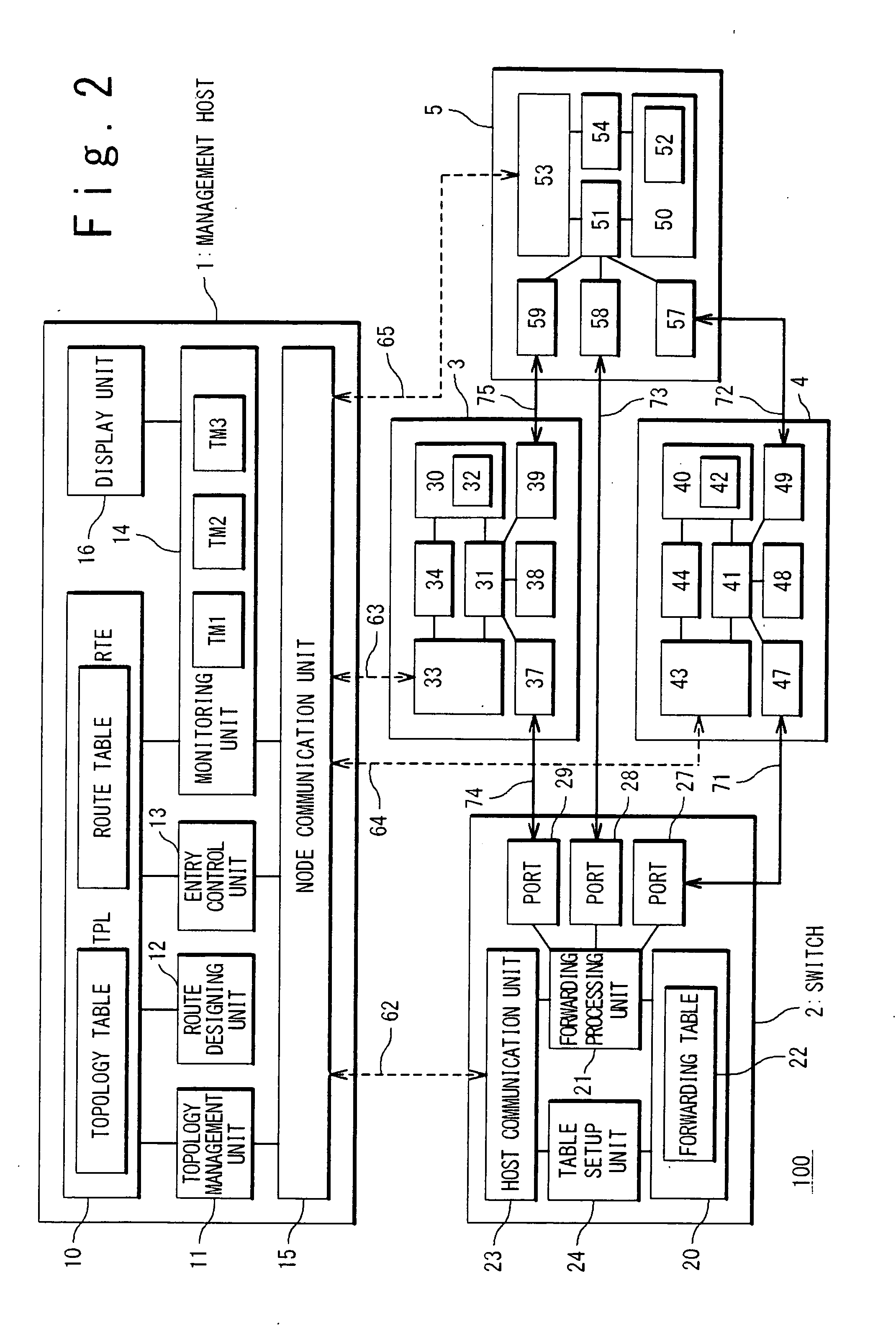
[0079]FIG. 2 is a block diagram showing a configuration of the communication network management system 1 according to the first exemplary embodiment. A management host 1 (Openflow Controller) in FIG. 2 corresponds to the management computer 1 in FIG. 1. Switches 2 to 5 (Openflow Switch) in FIG. 2 correspond to the nodes 2 to 5 in FIG. 1, respectively.

[0080]The management host 1 has a storage unit 10, a topology management unit 11, a route designing unit 12, an entry control unit 13, a monitoring unit 14, a node communication unit 15 and a display unit 16. The node communication unit 15 is connected to the switches 2 to 5 through the control links 62 to 65, respectively. The management host 1 can communicate bi-directionally with the switches 2 to 5 by using the node communication unit 15 and the control links 62 to 65.

[0081]The storage unit 10 is a storage device such as a RAM and an HDD. A topology table TPL and a route table RTE...

Example

2. Second Exemplary Embodiment

[0184]According to the above-described first exemplary embodiment, the forwarding table of each switch is reset as shown in FIGS. 16 to 19 at the Step S31 after the failure occurrence is detected. According to a second exemplary embodiment of the present invention, the forwarding table of each switch is preliminarily set as shown in FIGS. 16 to 19, before the failure occurrence is detected. In other words, the forwarding destination indicated by the forwarding table of each switch includes the management host 1 (HOST), before the failure occurrence is detected. For example, at the initial setting, the forwarding table of each switch is set up as shown in FIGS. 16 to 19.

[0185]FIG. 22 is a flow chart showing a communication network management method according to the second exemplary embodiment. According to the present exemplary embodiment, Step S13′ is executed instead of the above-described Step S13. In Step S13′, the entry control unit 13 of the manage...

Example

3. Third Exemplary Embodiment

[0189]According to a third exemplary embodiment of the present invention, after the location of failure is identified, the transfer of the forward check frame FRA or the backward check frame FRB continues by jumping the location of failure. FIG. 25 is a flow chart showing a communication network management method according to the third exemplary embodiment. The processing before the identification of the location of failure (Step S30 or S30′) is the same as in the case of the foregoing first or second exemplary embodiment. Step S40 is added after the identification of the location of failure.

[0190]Step S40:

[0191]Let us consider a case where the location of failure is the physical link 72 between the switch 4 and the switch 5 as in the case of the foregoing embodiment. Currently, it has been confirmed that the forward check frame FRA is normally transferred from the start-point switch 2 to the switch 4 along the forward route and the backward check frame ...


PUM


Abstract

A communication network management system has: a communication network including a plurality of nodes and a plurality of links connecting between the plurality of nodes; and a management computer that manages the communication network. The management computer has: a storage means in which a route information indicating a transfer route of frames in the communication network is stored; and a monitoring means configured to perform, based on the route information, transmission and reception of frames to and from the communication network. The monitoring means transmits a frame to the transfer route. Each of the plurality of nodes, when receiving a frame, not only forwards the received frame along the transfer route but also sends a reply to the management computer. The monitoring means identifies a location of failure occurrence on the transfer route, based on reception state of the reply from the plurality of nodes.

Description

TECHNICAL FIELD[0001]The present invention relates to a communication network management technique that performs centralized management of a communication network by using a management computer.BACKGROUND ART[0002]In recent years, a communication network has a significant role as a social infrastructure that provides various services, and failure of the communication network has an incalculable impact on users. Therefore, health-checking of the communication network has become a very important issue.[0003]Patent Literature 1 (International Publication WO2005 / 048540) discloses a technique that uses a keep-alive frame to detect a failure in a communication network. More specifically, in a communication system in which a plurality of base nodes perform communication through one or more relay node, each base node transmits a keep-alive frame that is broadcasted by the relay node. Here, the plurality of base nodes mutually transmit and receive the keep-alive frame and detect failure by m...

Claims


Application Information

Patent Timeline
IPC IPC(8): G06F15/173H04L45/02H04L45/28H04L45/42
CPCH04L41/0213H04L43/0811H04L45/026H04L41/069H04L45/28H04L45/42H04L45/26H04L41/40H04L43/20
Inventor ENOMOTO, NOBUYUKIKOIDE, TOSHIOSHIMONISHI, HIDEYUKI
Owner NEC CORP
Why Eureka
Try Eureka