

Support Truss for Hinged Overhead Door
- Summary
- Abstract
- Description
- Claims
- Application Information
AI Technical Summary
Benefits of technology
Problems solved by technology
Method used
Image

Examples
Embodiment Construction
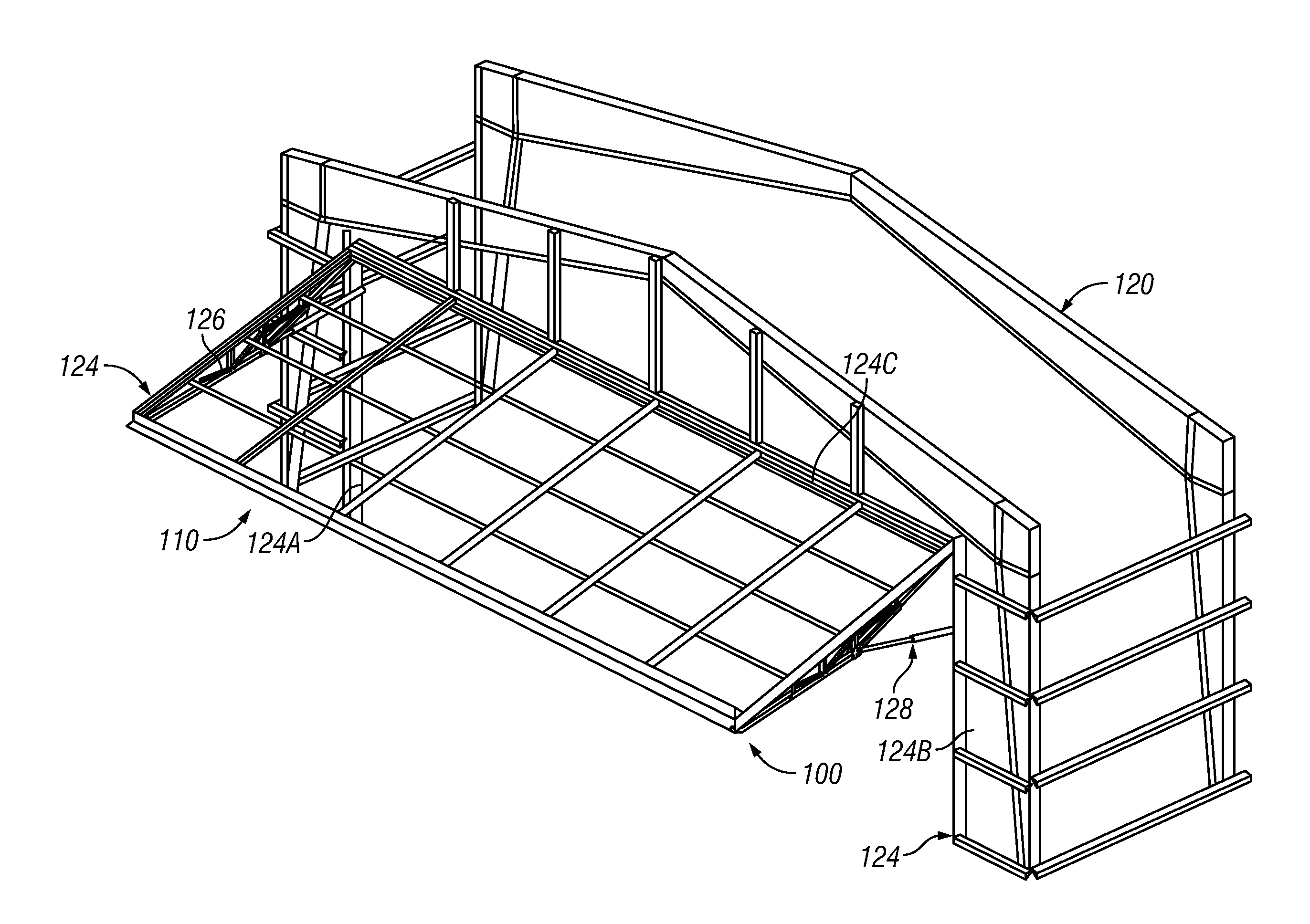
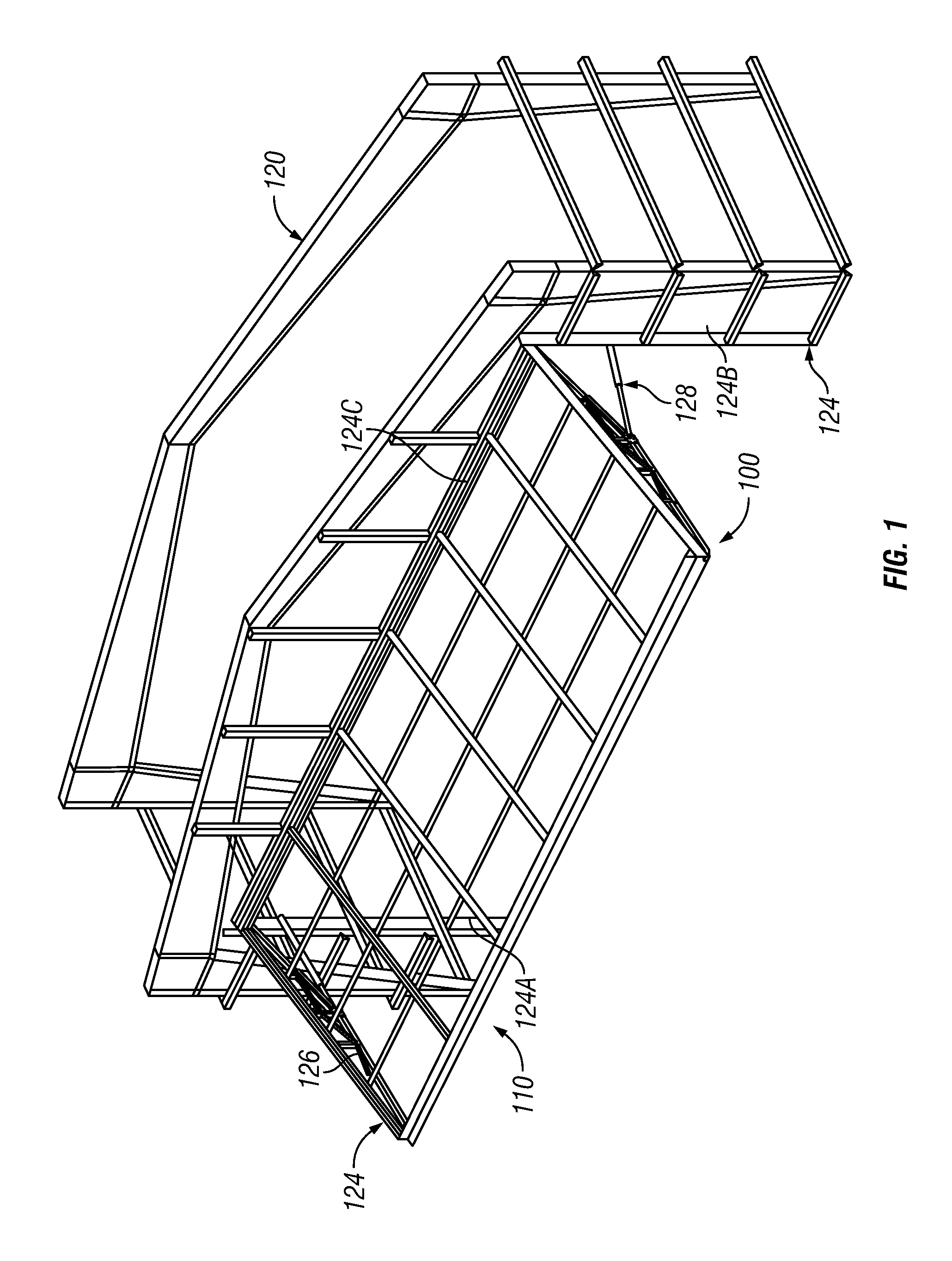
[0026]Certain embodiments as disclosed herein provide for support trusses for an overhead door such as a hangar door, and for an overhead door assembly incorporating support trusses, which may be side trusses located at opposite sides of the door. Additional support trusses may be located at other positions on the door.
[0027]After reading this description it will become apparent to one skilled in the art how to implement the invention in various alternative embodiments and alternative applications. However, although various embodiments of the present invention will be described herein, it is understood that these embodiments are presented by way of example only, and not limitation. As such, this detailed description of various alternative embodiments should not be construed to limit the scope or breadth of the present invention.
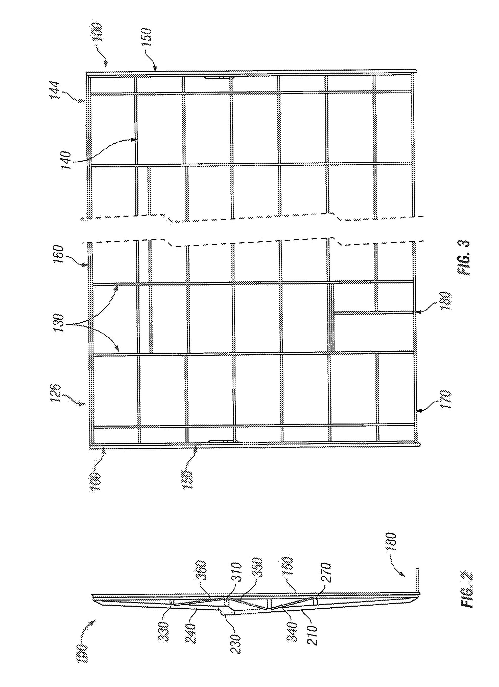
[0028]FIG. 1 illustrates one embodiment of an overhead door assembly 110 mounted in an opening of a building 120 such as a hangar or the like, while FIGS. 2 ...
PUM
 Abstract
Description
Claims
Application Information