Magnetron Plasma Sputtering Apparatus

a sputtering apparatus and magnetron technology, applied in the direction of vacuum evaporation coating, electrolysis components, coatings, etc., can solve the problems of low yield the inability of ions to reach the substrate, so as to enhance the overall sputtering effect of the magnetron plasma sputtering apparatus

Inactive Publication Date: 2011-09-29
NAT SUN YAT SEN UNIV
View PDF9 Cites 7 Cited by
  • Summary
  • Abstract
  • Description
  • Claims
  • Application Information

AI Technical Summary

Benefits of technology

[0008]The primary objective of the present invention is to provide a magnetron plasma sputtering apparatus that includes a guiding coil between a target and a substrate to enhance the overall sputtering effect of the magnetron plasma sputtering apparatus.

Problems solved by technology

However, some of the ions may not be able to reach the substrate 8 and shift from the sputtering path due to insufficient momentum.
The sputtering operation on the substrate 8 cannot be achieved, resulting in low yield of the magnetron plasma sputtering apparatus 9.

Method used


Image

  • Magnetron Plasma Sputtering Apparatus
  • Magnetron Plasma Sputtering Apparatus
  • Magnetron Plasma Sputtering Apparatus

Examples


Embodiment Construction

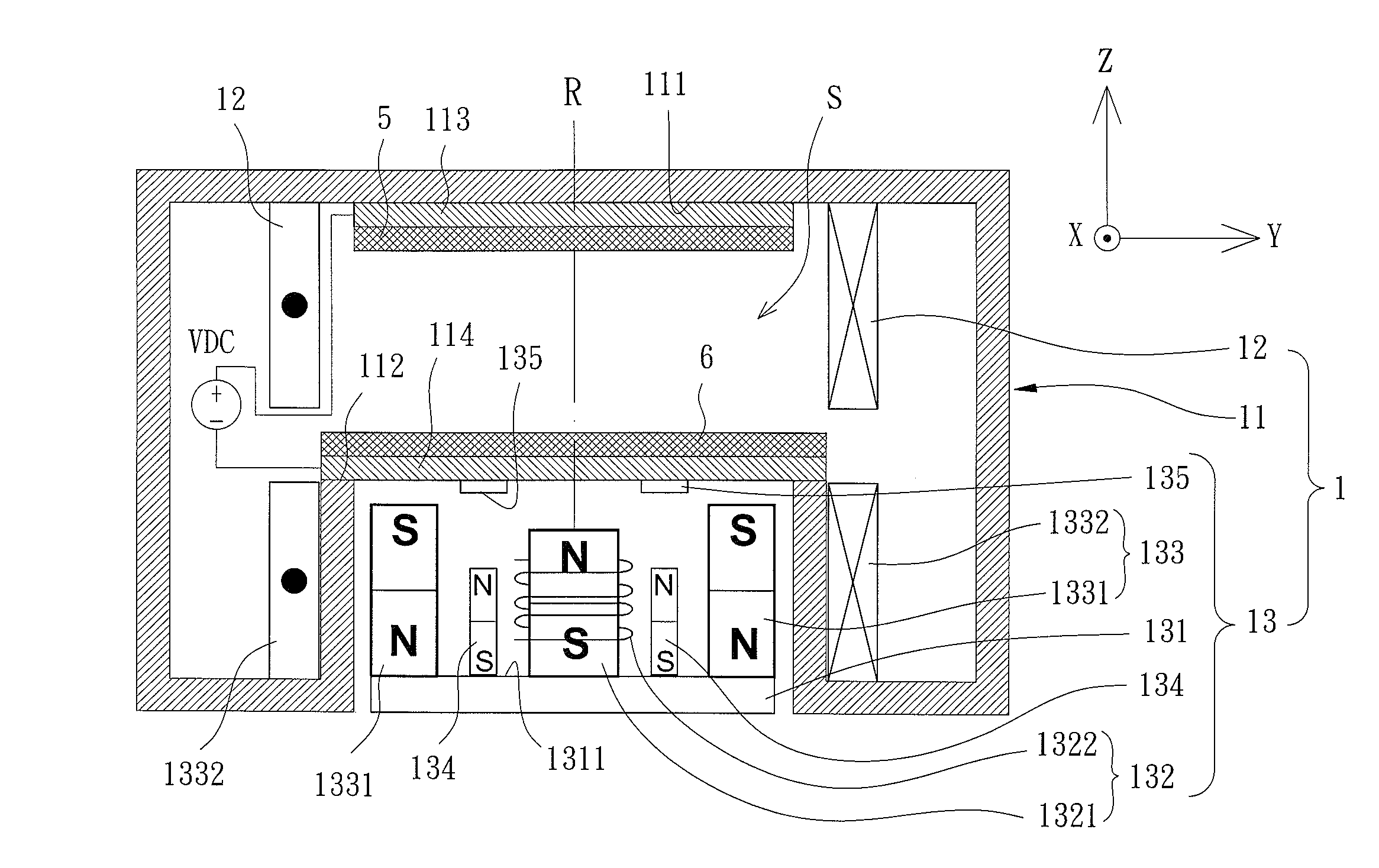
[0018]A magnetron plasma sputtering apparatus 1 of a preferred embodiment according to the present invention is shown in FIGS. 3 and 4. The magnetron plasma sputtering apparatus 1 is adapted to receive a target 6 for performing sputtering on a substrate 5. The magnetron plasma sputtering apparatus 1 includes a sputtering chamber 11, a guiding coil 12, and a magnetron device 13. The sputtering chamber 11 includes a loading portion 111 and an engaging portion 112 opposite to the loading portion 111. The engaging portion 112 is spaced from the loading portion 111 in a first direction Z. An anode plate 113 is mounted to the loading portion 111, and the substrate 5 is mounted to the anode plate 113. A cathode plate 114 is mounted to the engaging portion 112, and the target 6 is mounted to the cathode plate 114. The anode plate 113 and the cathode plate 114 are respectively connected to positive and negative poles of a DC power source VDC. A sputtering space S is defined between the loadi...


PUM

PropertyMeasurementUnit
magnetizationaaaaaaaaaa
magnetic fieldaaaaaaaaaa
forceaaaaaaaaaa

Abstract

A magnetron plasma sputtering apparatus includes a sputtering chamber having a loading portion and an engaging portion opposite to the loading portion. A substrate is mounted to the loading portion. A target is mounted to the engaging portion. A sputtering space is defined between the loading portion and the engaging portion. A reference line extends through the loading portion, the sputtering space, and the engaging portion in sequence. A guiding coil surrounds the sputtering space with the reference line located in the center. A magnetron device is located at a side of the sputtering chamber adjacent to the engaging portion. The magnetron device has a magnetization side facing the engaging portion.

Description

BACKGROUND OF THE INVENTION[0001]1. Field of the Invention[0002]The present invention relates to a magnetron plasma sputtering apparatus and, more particularly, to a magnetron plasma sputtering apparatus that proceeds with plasma sputtering through magnetic control.[0003]2. Description of the Related Art[0004]A magnetron plasma sputtering apparatus generally affects charged particles with a magnetic field to effectively impact a target. The atoms on a surface of the target exchange with kinetic energy with the high-energy charged particles to generate ion sputtering. The ions flying away from the target results in the impact deposit on a substrate to form a film.[0005]FIGS. 1 and 2 show a conventional magnetron plasma sputtering apparatus 9 including a sputtering chamber 91 and a magnetron 92. The sputtering chamber 91 includes a loading portion 911 and an engaging portion 912 opposite to the loading portion 911. An anode plate 913 is mounted to the loading portion 911, and a substr...

Claims


Application Information

Patent Timeline
Patent Type & Authority Applications(United States)
IPC IPC(8): C23C14/35
CPCH01J37/3405C23C14/35H01J37/3458C23C14/351
Inventor LIU, CHENG-TSUNG
Owner NAT SUN YAT SEN UNIV
Why Eureka
Try Eureka