Exhaust manifold gasket with spring steel embossed metal and graphite insulator

a technology of graphite insulator and exhaust manifold, which is applied in the direction of engine sealing, machine/engine, engine sealing arrangement, etc., can solve the problems of gasket being subject to constant pressure change, gasket being known to be put under additional stress, and difficulty in sealing the gap, etc., to achieve significant stress reduction

Inactive Publication Date: 2011-09-29
DANA AUTOMOTIVE SYST GRP LLC
View PDF19 Cites 25 Cited by
  • Summary
  • Abstract
  • Description
  • Claims
  • Application Information

AI Technical Summary

Benefits of technology

The present invention is directed toward an exhaust manifold gasket comprising a core, at least one insulating layer, and an embossed layer. The core is made of a metal material and has two sides with at least one side having a plurality of projections and may include an adhesive layer. The insulating layer has a first and a second surface and may be made of graphite. The first surface of the insulating layer is attached to the core by either the projections or an adhesive layer. The second surface contacts the embossed layer. The embossed layer is a metallic flange comprised of a lower leg, a convex face, and an upper leg. The convex face connects the upper and lower legs to prevent exhaust gas leakage between the core and the facing layer. The upper leg is parallel to the lower leg and connected at one end to the convex face. Additional embodiments of this invention may include a coating on the flange and / or a flange ring. Finally, another embodiment of the invention may comprise a metallic core, an insulation layer and a lower beaded metallic layer.
In accordance with the present invention, it has been discovered that stress is significantly decreased at the sealing ports, and the embossed metal layers provides more recovery properties than a graphite layer by itself.

Problems solved by technology

Sealing the gap, however, can be difficult because the head, manifold and gasket all move due to pressure and temperature fluctuations, which results in the gasket being subjected to constant pressure changes.
There are also problems due to thermal expansion and thermal contraction, which occurs when the temperatures varies in the cylinder head base.
The areas around these openings are known to be put under additional stresses and leakage is common.
Traditionally, multi-layered or single-layered embossed metal provides poor adaptability and limited insulative properties.
Thermal motion, resulting from hot exhaust gases, increasing combustion pressure and steep thermal swings, and sheer stresses are created in this area and the multi or single layered embossed metals become over compressed and do not adequately stop the leakage.
The thermal motion eventually causes poor recovery and burn out from the joint movement between the head and the manifold.

Method used


Image

  • Exhaust manifold gasket with spring steel embossed metal and graphite insulator
  • Exhaust manifold gasket with spring steel embossed metal and graphite insulator
  • Exhaust manifold gasket with spring steel embossed metal and graphite insulator

Examples


Embodiment Construction

It is to be understood that the invention may assume various alternative orientations and step sequences, except where expressly specified to the contrary. It is also to be understood that the specific devices and processes illustrated in the attached drawings, and described in the following specification are simply exemplary embodiments of the inventive concepts defined in the appended claims. Hence, specific dimensions, directions or other physical characteristics relating to the embodiments disclosed are not to be considered as limiting, unless the claims expressly state otherwise.

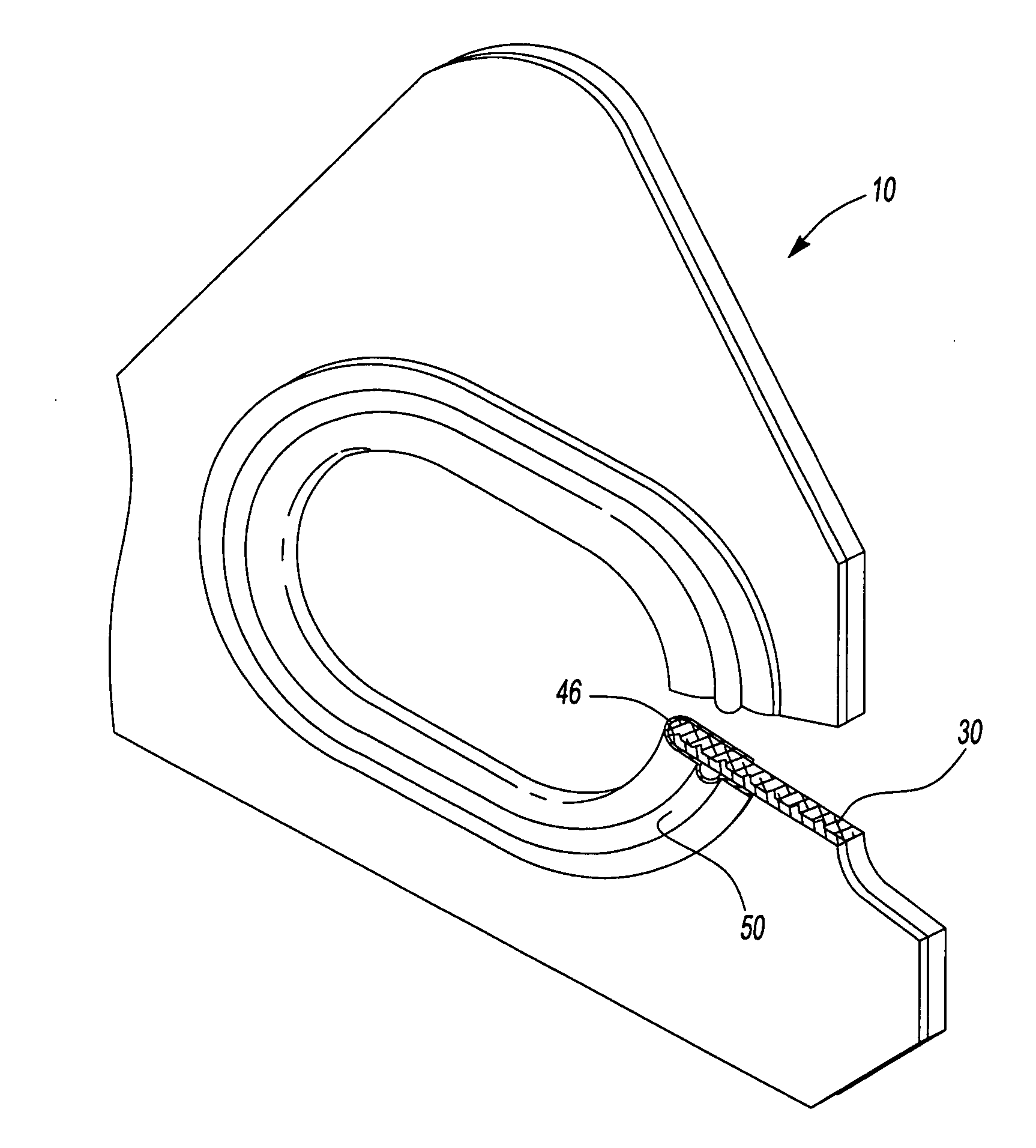
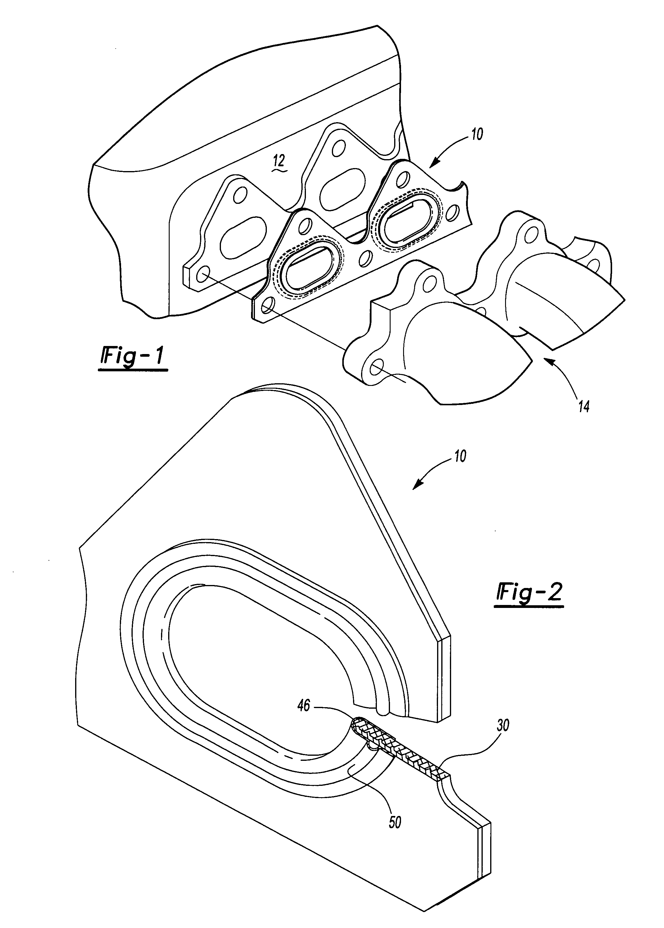
An exhaust manifold gasket 10 as shown in FIG. 1 is positioned between a cylinder head 12 and an exhaust manifold 14, so as to create an air tight seal when the two structures are bolted together. The exhaust manifold gasket is manufactured in accordance with the various shapes of cylinder head and exhaust manifolds, and includes numerous openings, such as exhaust gas openings and bolt holes. Various se...


PUM


Abstract

The present invention relates to an exhaust manifold gasket having a metallic core, at least one insulating layer, and an embossed layer. The metallic core has two sides with at least one side having a plurality of projections. The insulating layer has two sides, with the first side contacting the projections of the metallic core and the second side contacting the embossed layer. The embossed layer is a metallic flange having a lower leg, a convex face, and an upper leg.

Description

RELATED APPLICATIONSNot ApplicableFIELD OF THE INVENTIONThe present invention relates to a gasket for use in internal combustion engines, specifically an exhaust manifold gasket inserted between a cylinder head and an exhaust manifold.BACKGROUND OF THE INVENTIONGaskets essentially are used to seal and prevent leakage between two parts. Exhaust manifold gaskets for internal combustion engines seal the gap between the cylinder head and the exhaust manifold. Sealing the gap, however, can be difficult because the head, manifold and gasket all move due to pressure and temperature fluctuations, which results in the gasket being subjected to constant pressure changes. There are also problems due to thermal expansion and thermal contraction, which occurs when the temperatures varies in the cylinder head base. There are also multiple openings in the head and the manifold for exhaust gases and bolts holes. The areas around these openings are known to be put under additional stresses and leaka...

Claims


Application Information

Patent Timeline
Patent Type & Authority Applications(United States)
IPC IPC(8): F02F11/00
CPCF01N13/102F16J2015/0862F16J15/0818F01N13/1827
Inventor SHAVER, KEVINMOCKENHAUPT, MARTIN
Owner DANA AUTOMOTIVE SYST GRP LLC
Why Eureka
Try Eureka