Stator arrangement for an electromechanical transducer, electromechanical transducer and wind turbine

a technology of electromechanical transducer and stator, which is applied in the direction of electric generator control, magnetic circuit shape/form/construction, magnetic circuit rotating parts, etc. it can solve the problems of damage to generator components and the disadvantage of efficiency and durability of conventional generators, so as to improve the efficiency of the electromechanical transducer, the effect of eliminating or constant air gap siz

Inactive Publication Date: 2011-09-29
SIEMENS AG
View PDF13 Cites 10 Cited by
  • Summary
  • Abstract
  • Description
  • Claims
  • Application Information

AI Technical Summary

Benefits of technology

[0024]According to an embodiment the coil is spaced apart from the magnet element in the axial direction. Thereby, an axial magnetic flux generator may be provided that may substantially eliminate or at least reduce traditional cogging issues observed in radial magnetic flux generators. In particular, the stator arrangement may follow any deflection of the rotor arrangement in the axial direction thereby maintaining a constant air gap size between magnet elements and corresponding coils. That the stator arrangement and thus the coils follow any deflection of the rotor arrangement may be due to the flexible element connecting the base structure to the coil holder flexibly relative to each other. In particular, the flexible element may allow sufficient freedom of movement or displacement for the stator arrangement primarily in the axial direction. In other embodiments the flexible element may allow movement of the coil holder and thus the coils in another direction or in plural other directions, such as the radial direction.
[0025]According to an embodiment the electromechanical transducer further comprises a rotor sliding surface arranged at the rotor arrangement and a coil holder sliding surface arranged at the coil holder, wherein the rotor sliding surface and the coil holder sliding surface are adapted to, upon rotating of the rotor, slide relative to each other such that a size of a gap between the coil...

Problems solved by technology

However, any misalignments and/or any movements or deflections of the rotor arrangement relative to the stator arrangement may result in alternating axial flux and may even result in damage of components of the generator.
For generators having increased diameters this problem may be even more severe, as even a small misalignment of the rotation axis of the rotor arrangement may resul...

Method used


Image

  • Stator arrangement for an electromechanical transducer, electromechanical transducer and wind turbine
  • Stator arrangement for an electromechanical transducer, electromechanical transducer and wind turbine
  • Stator arrangement for an electromechanical transducer, electromechanical transducer and wind turbine

Examples


Embodiment Construction

[0038]The illustration in the drawing is schematically. It is noted that in different figures, similar or identical elements are provided with the same reference signs or with reference signs, which are different from the corresponding reference signs only within the first digit.

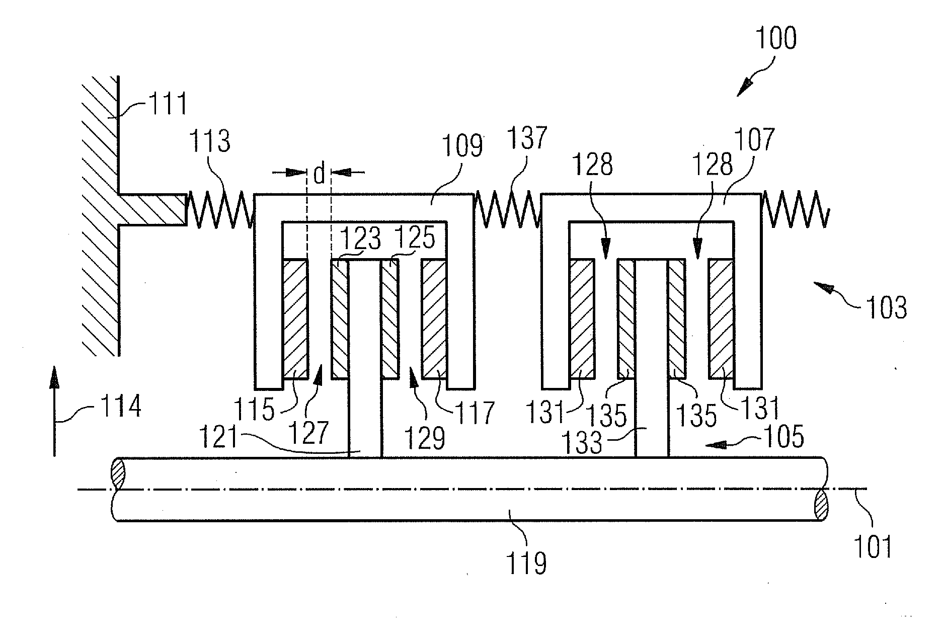
[0039]FIG. 1 schematically illustrates a part of generator 100 in a cross-sectional view representing a cross-section in a plane including the rotation axis 101. The generator 100 comprises a stator arrangement 103 and a rotor arrangement 105.

[0040]The stator arrangement 103 comprises a coil holder 107 having a U-shape in cross-section and a coil holder 109 also having a U-shape in cross-section. In other words, the coil holders 107 and 109 may represent two yokes.

[0041]The stator arrangement further comprises a base structure 111. The coil holder 109 is connected to the base structure 111 by means of a flexible element 113 connecting the base structure to the coil holder flexibly relative to each other. In ...


PUM


Abstract

A stator arrangement for an electromechanical transducer is provided. The stator arrangement includes a base structure, a coil holder, a coil mounted at the coil holder; and a flexible element connecting the base structure to the coil holder flexibly relative to each other. Further, an electromechanical transducer is provided that includes the above-mentioned stator arrangement and a rotor arrangement rotatable relative to the base structure around an axial direction. Still, further, a wind turbine is provided that includes the above-mentioned electromechanical transducer as a generator.

Description

FIELD OF INVENTION[0001]The present invention relates to a stator arrangement for an electromechanical transducer, to an electromechanical transducer utilizing the stator, and to a wind turbine utilizing the electromechanical transducer as a generator.ART BACKGROUND[0002]Electromechanical transducers are machines which convert electrical energy into mechanical energy or vice versa, such as an electrical motor or a generator. While for example an electric motor converts electrical energy into mechanical energy, an electric generator converts mechanical energy into electrical energy. However, both types of electromechanical transducers use a magnetic field in conjunction with a conductor to achieve the energy conversion. In particular, a changing magnetic flux generated by the magnetic field may induce a voltage between points of the conductor resulting in a current representing electrical energy.[0003]An electromechanical transducer may comprise a stator arrangement and a rotor arran...

Claims


Application Information

Patent Timeline
IPC IPC(8): H02K1/18F03D9/00
CPCH02K1/182H02K7/088H02K16/00H02K7/1838H02K2201/03Y02E10/725H02K21/24Y02E10/72
Inventor STIESDAL, HENRIK
Owner SIEMENS AG
Why Eureka
Try Eureka