Metal detector sensor head

a metal detector and sensor head technology, applied in the field of metal detectors, can solve the problems of adversely affecting the achieve the effects of reducing the effective sensitivity of the metal detector, reducing the induction of eddy current, and high magnetic permeability

Inactive Publication Date: 2011-09-29
MINELAB ELECTRONICS
View PDF4 Cites 6 Cited by
  • Summary
  • Abstract
  • Description
  • Claims
  • Application Information

AI Technical Summary

Benefits of technology

According to an aspect of the present invention, there is provided a method for improving the sensitivity of a metal detector, the metal detector capable of transmitting transmit magnetic fields and receiving reflected magnetic fields for detecting a target in a ground, the method including:
The effective sensitivity of a metal detector might be reduced if the varying intensity of magnetic field reflected by magnetic matrices induces eddy currents of varying initial magnitudes in conductive components that are within the sensor head of the detector. This invention is a means of reducing the induction of eddy currents in conductive elements of a sensor head.
The aim of this invention is to remove the effect of small pieces of conductive material, located within or close to the sensor head, being seen as sought targets as the sensor head is moved over magnetic matrix. The means is to surround the conductive material with material with high magnetic permeability and low losses in a time-varying magnetic field, say low-loss ferrite. This will prevent the reflected field from illuminating the conductive material so eddy currents are not generated. The ferrite, with its low losses, responds to the time-varying field, a combination of directly transmitted field and that reflected by the matrix and any targets it contains, with such little loss as to make its response instantaneous as far as the metal detector is concerned. As long as its position with respect to the windings is fixed, it does not temporally modulate the field at any point in space.

Problems solved by technology

identifying at least one electrically conductive element of the metal detector located within the effective ranges of the reflected magnetic fields, wherein an intensity of the reflected magnetic fields, entering the at least one electrically conductive element, changes because of the ground and / or the target, and the said intensity change adversely affects the sensitivity of the metal detector; and

Method used


Image

  • Metal detector sensor head
  • Metal detector sensor head
  • Metal detector sensor head

Examples


Embodiment Construction

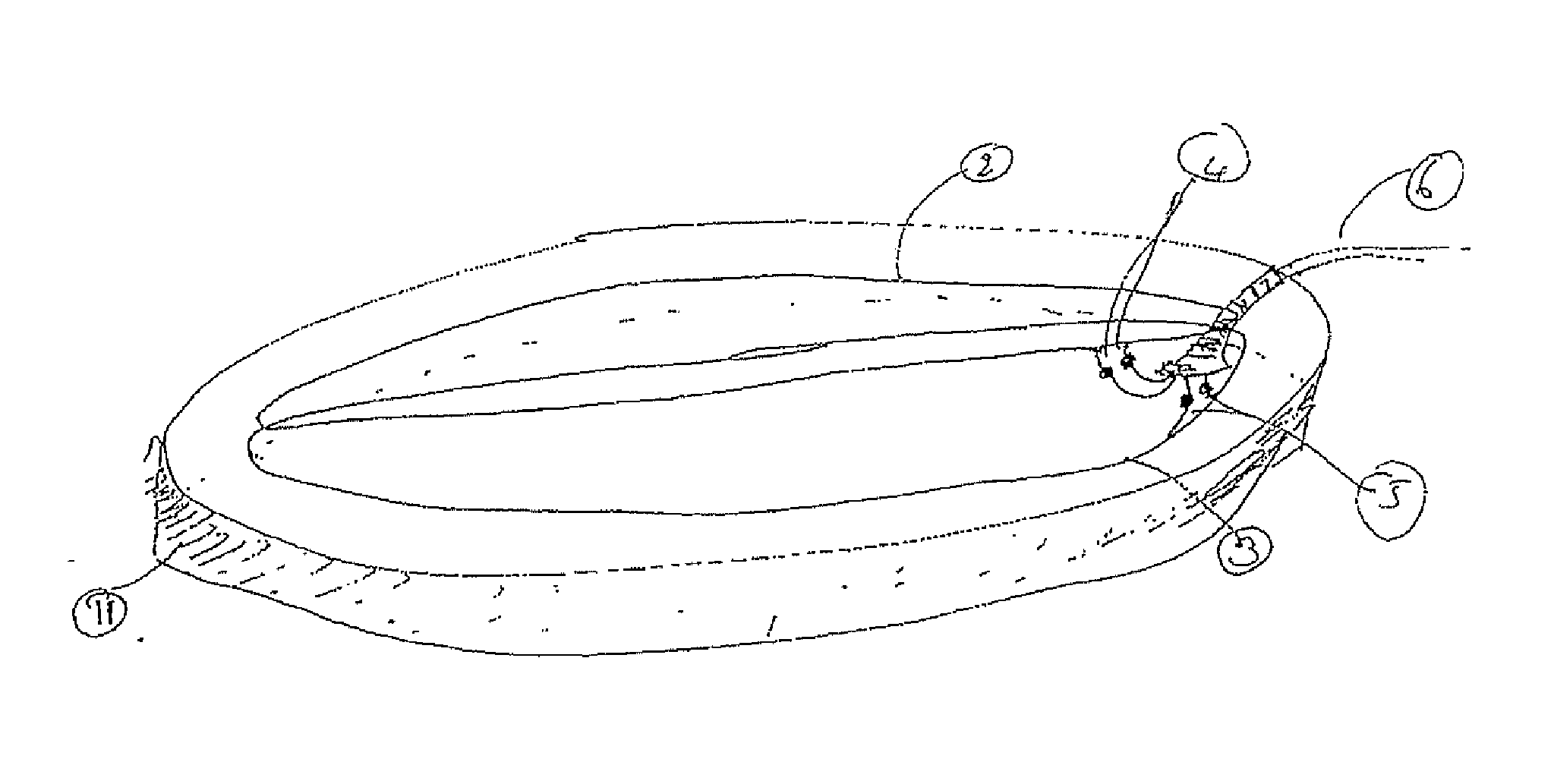
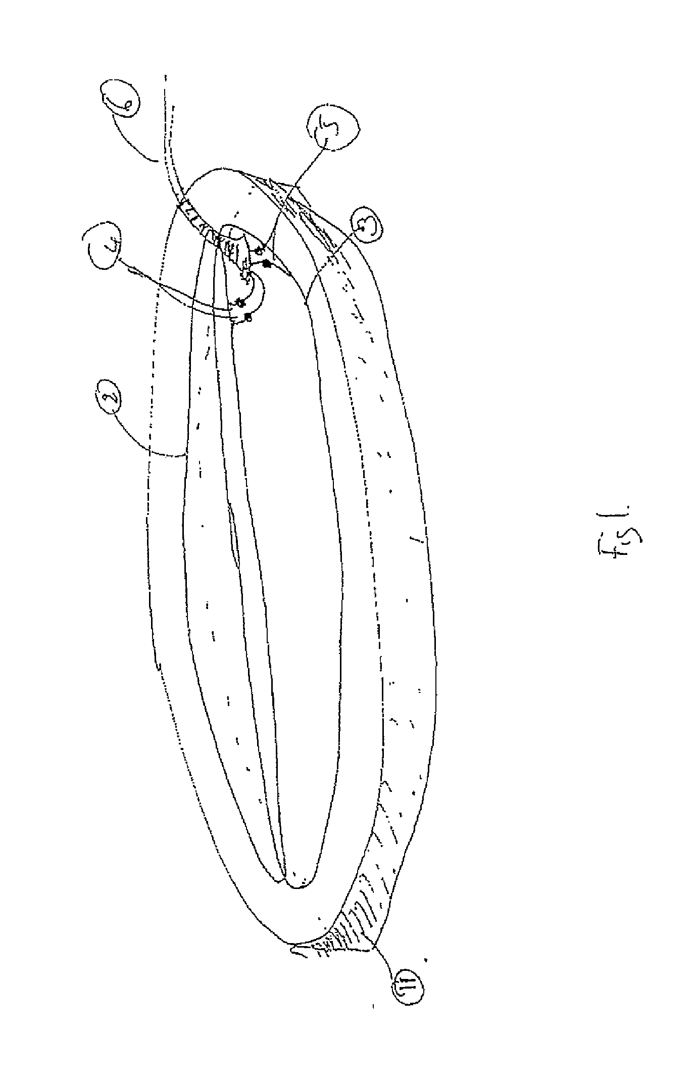
FIG. 1 shows a representation of an exemplar of a sensor head for a hand-held motion metal detector. The outer shell (1) houses the Rx winding (2), the Tx winding (3), the shape of which are one of many suitable for their purpose. The two free ends of the windings (2&3) are connected with soldered joints (4&5, respectively) to the cables with the lead (6) that connects the sensor head to the control box (not represented). The windings (2&3) are often made of Litzendraht wire, or at least fine, individually insulated, parallel strands of conductor, in order to prevent the generation of eddy currents with relatively long time constants in the windings, which is a preferred arrangement.

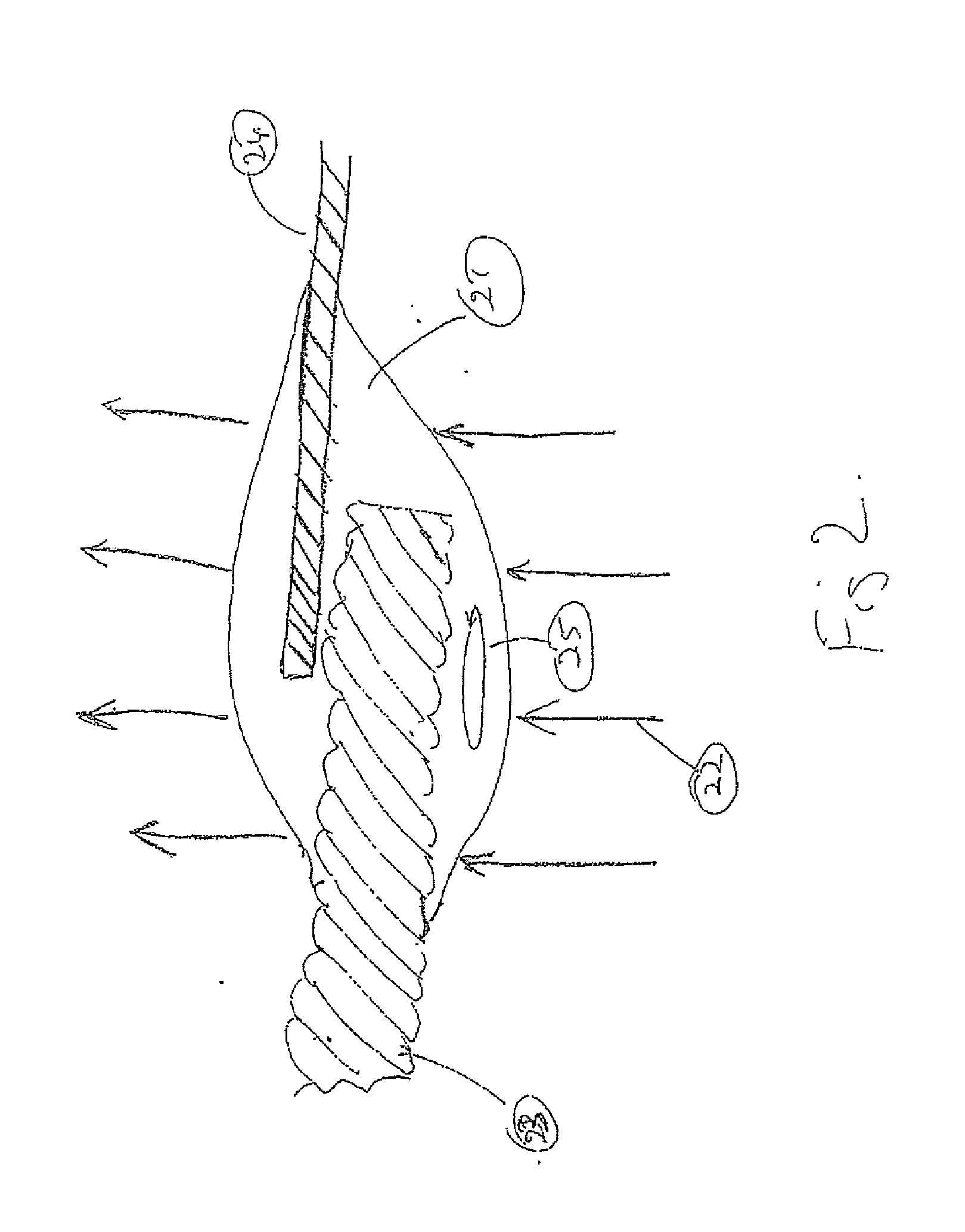
FIG. 2 shows a representation of a cross-section of a solder joint used within a sensor head. A time-varying magnetic field is represented by the field lines (22). The cable of the winding in the sensor head is shown (23), along with the cable to which it is connected (24) with the solder joint (21). A s...


PUM


Abstract

A metal detector includes means for reducing the induction of eddy currents in conductive elements of a sensor head. The aim of this invention is to remove the effect of small pieces of conductive material, located within or close to the sensor head, being seen as sought targets as the sensor head is moved over magnetic matrix. The means is to surround the conductive material with material with high magnetic permeability and low losses in a time-varying magnetic field, say low-loss ferrite. This will prevent the reflected field from illuminating the conductive material so eddy currents are not generated.

Description

TECHNICAL FIELDThis invention pertains to metal detectors, particularly those that transmit time-varying magnetic fields to induce eddy currents in both ferrous and non-ferrous metallic targets, then detect the magnetic fields concomitant with the induced eddy currents.BACKGROUND OF THE INVENTIONOver many decades there have been improvements in the performance of metal detectors that transmit time-varying magnetic fields to illuminate sought targets. One motive for improvement is the desire for greater sensitivity to a greater range of targets. To this end, improvements such as higher dynamic range in the receive electronics, improvement in the ability to reject the signal from mineralised ground and increased sensitivity to smaller targets have been developed. At various times, an improvement has exposed deficiencies in aspects of the detector other than the electronics.This invention deals with a deficiency in the design of coils, or sensing heads, of metal detectors. It has appli...

Claims


Application Information

Patent Timeline
Patent Type & Authority Applications(United States)
IPC IPC(8): G01R33/18
CPCG01R33/1215G01V3/107G01R33/1223
Inventor JONES, ALEXANDER LEWIS
Owner MINELAB ELECTRONICS
Why Eureka
Try Eureka