

Projector, projector system, data output method of projector, and data output method of projector system
a projector system and projector technology, applied in the field of projector system data output method, etc., can solve the problem of difficult to adjust the projection timing between the plurality of projectors, complicating the configuration of the entire projector system, and a relatively long interval of calculating the synchronization adjustment time. to achieve the effect of reducing the time lag of output timing and enhancing data transfer speed
- Summary
- Abstract
- Description
- Claims
- Application Information
AI Technical Summary
Benefits of technology
Problems solved by technology
Method used
Image

Examples
first embodiment
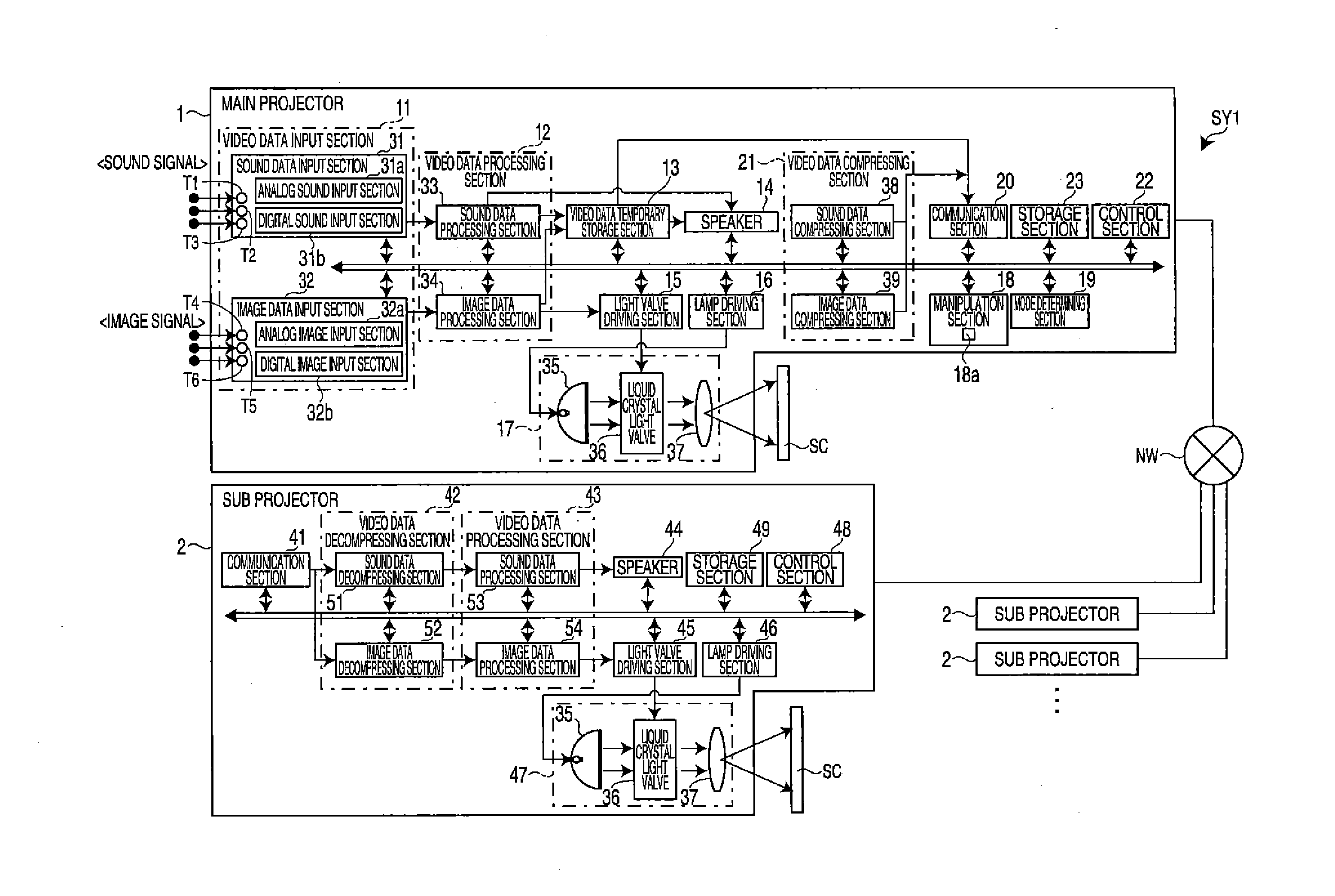
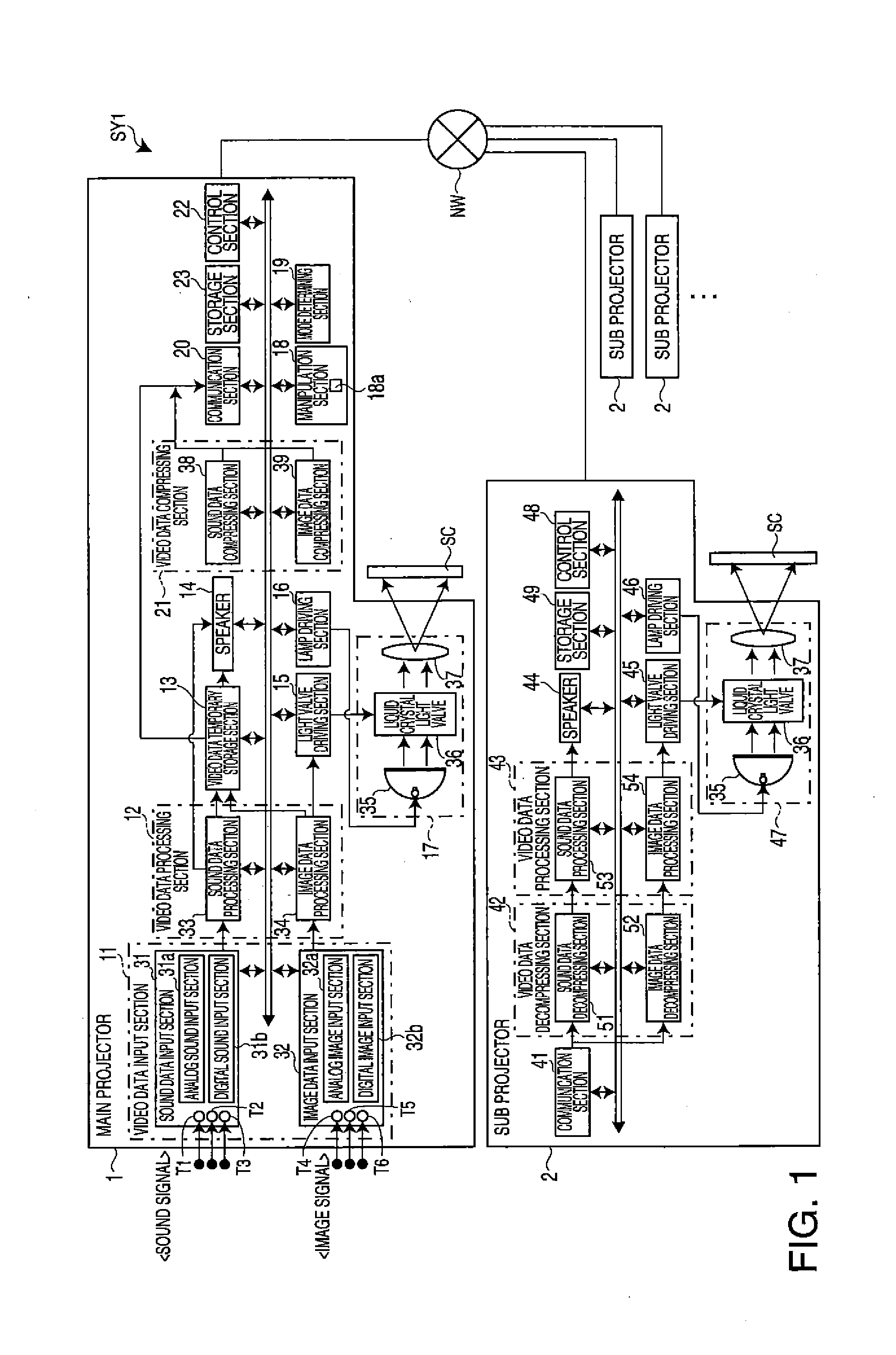
[0047]Hereinafter, a projector system which uses projector according to the invention and a data output method thereof will be described with reference to the accompanying drawings. As shown in FIG. 1, a projector system SY1 according to a first embodiment includes a main projector 1 (projector, first projector) and a plurality of sub projectors 2 (other projectors, second projectors) connected to the main projector 1 through a network NW (a state where three or more sub projectors 2 are connected is exemplified in FIG. 1). The main projector system SY1 transfers image data which is projected onto the main projector 1 and sound data which is synchronized with the projection of the image data to be output as sound (hereinafter, data obtained by synchronizing the image data with the sound data in synchronization with the image data to be output is referred to as “video data”) to each sub projector 2 to share the projection image and the sound between the main projector 1 and each sub ...
second embodiment
[0079]Next, a video output process (image projection process and sound output process) in a projector system SY2 according to a second embodiment of the invention will be described with reference to FIGS. 3 to 6. FIG. 3 is a control block diagram illustrating the projector system SY2 according to the second embodiment. A basic configuration thereof is the same as the projector system SY1 (see FIG. 1) according to the first embodiment, but it is different from the first embodiment in that synchronization processing sections 55 and 56 are further provided to the main projector 1 and the sub projector 2, and the main projector 1 adjusts an output timing of the video data of the main projector 1 by the operations of the respective sections and adjusts a transfer timing of the video data to each sub projector 2 to synchronize timings of the image projection and the sound output in the main projector 1 and each sub projector 2. The other configurations of the second embodiment are the sam...
third embodiment
[0111]Next, a video output process in a projector system SY3 according to a third embodiment of the invention will be described with reference to FIGS. 7 to 9. A basic device configuration in the projector system SY3 according to the third embodiment is the same as the projector system SY2 according to the second embodiment (see FIG. 3), but a method of synchronizing output timings of the video data in the main projector 1 and each sub projectors 2 is different from the projector systems SY1 and SY2 in the first embodiment and the second embodiment. Specifically, this embodiment is different from the first and second embodiments in that the main projector 1 and each sub projector 2 adjust output timings of the video data and the timings of the image projection and the sound output in the main projector 1 and each sub projector 2 are synchronized. The other configuration of the third embodiment is the same as in the projector systems SY1 and SY2 in the first and second embodiments.
[0...
PUM
 Abstract
Description
Claims
Application Information