Probe memory device and positioning method therefor

a technology of which is applied in the field of probe memory device and positioning method therefor, can solve the problems of affecting the quality of data recording, and unable to provide concrete descriptions,

Inactive Publication Date: 2007-02-08
HITACHI LTD
View PDF7 Cites 21 Cited by
  • Summary
  • Abstract
  • Description
  • Claims
  • Application Information

AI Technical Summary

Benefits of technology

[0037] (3) By adopting an electrostatic driven or electromagnetic driven actuator, it becomes possible ...

Problems solved by technology

With respect to these problems, the above-mentioned conventional technique does not provide concrete description regarding each driving process.
In addition, the above-mentioned conventional technique comes with the following problems.
As a result, it takes a time for an individual probe to move between memory areas, which poses a l...

Method used


Image

  • Probe memory device and positioning method therefor
  • Probe memory device and positioning method therefor
  • Probe memory device and positioning method therefor

Examples


first embodiment

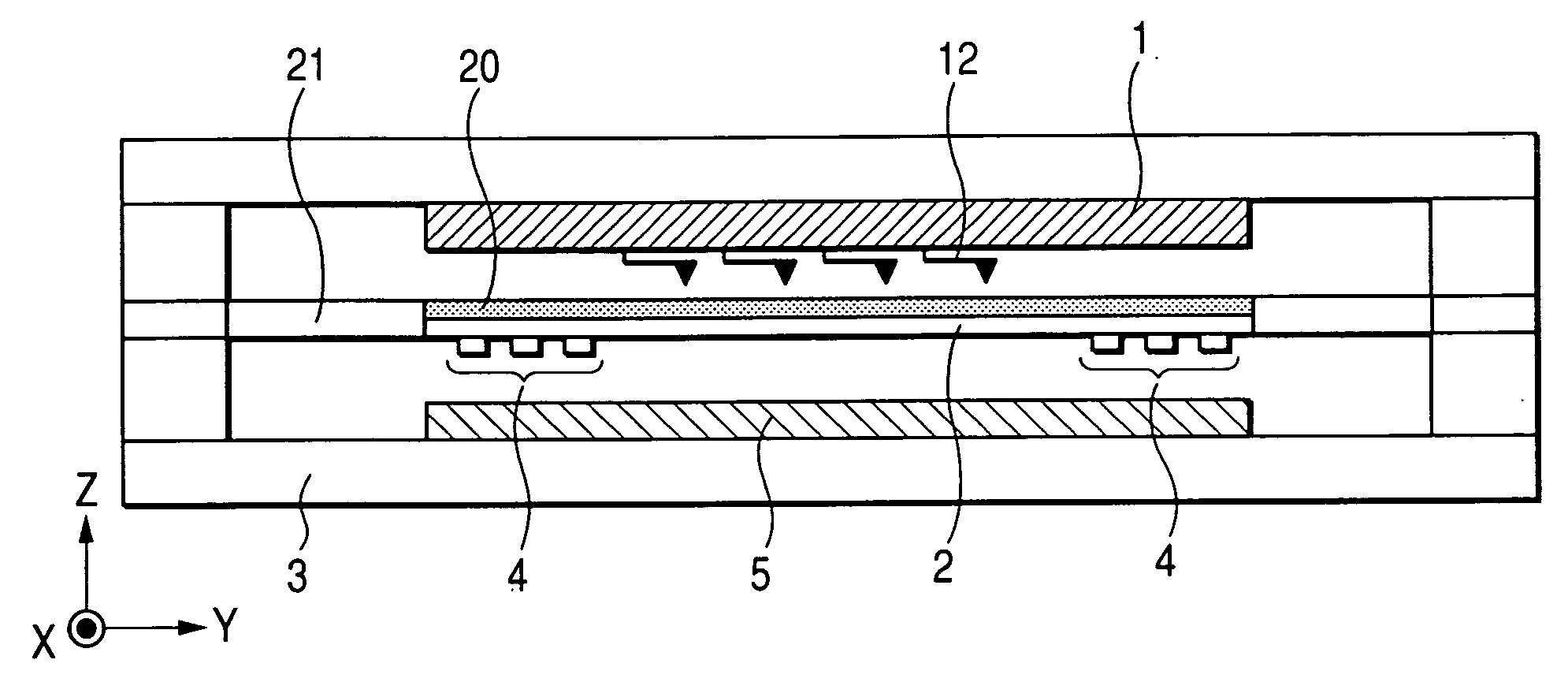
[0057]FIG. 1 is a sectional view showing a structure of a probe memory device using an X-Y electromagnetic actuator according to a first embodiment of this invention.

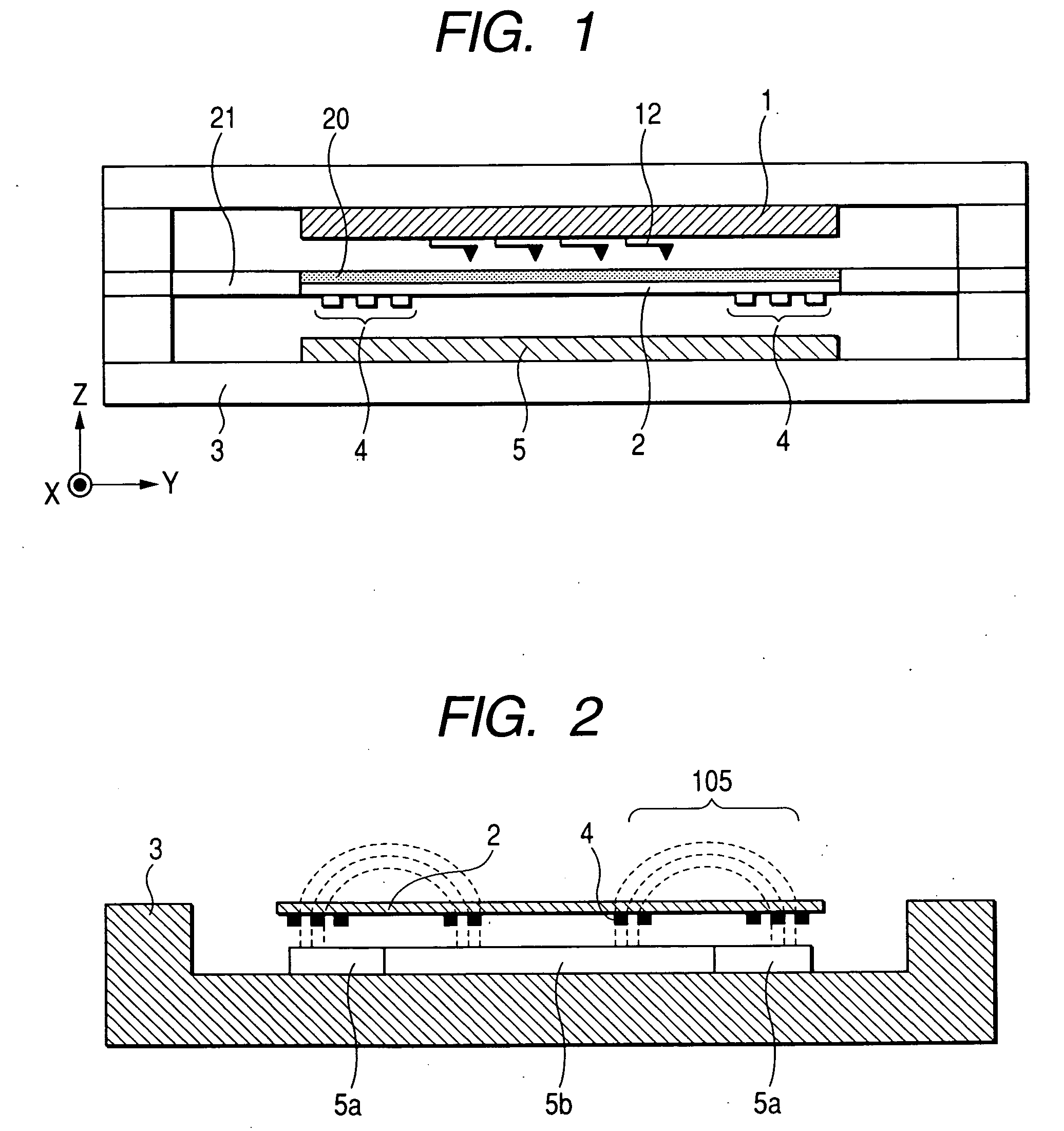
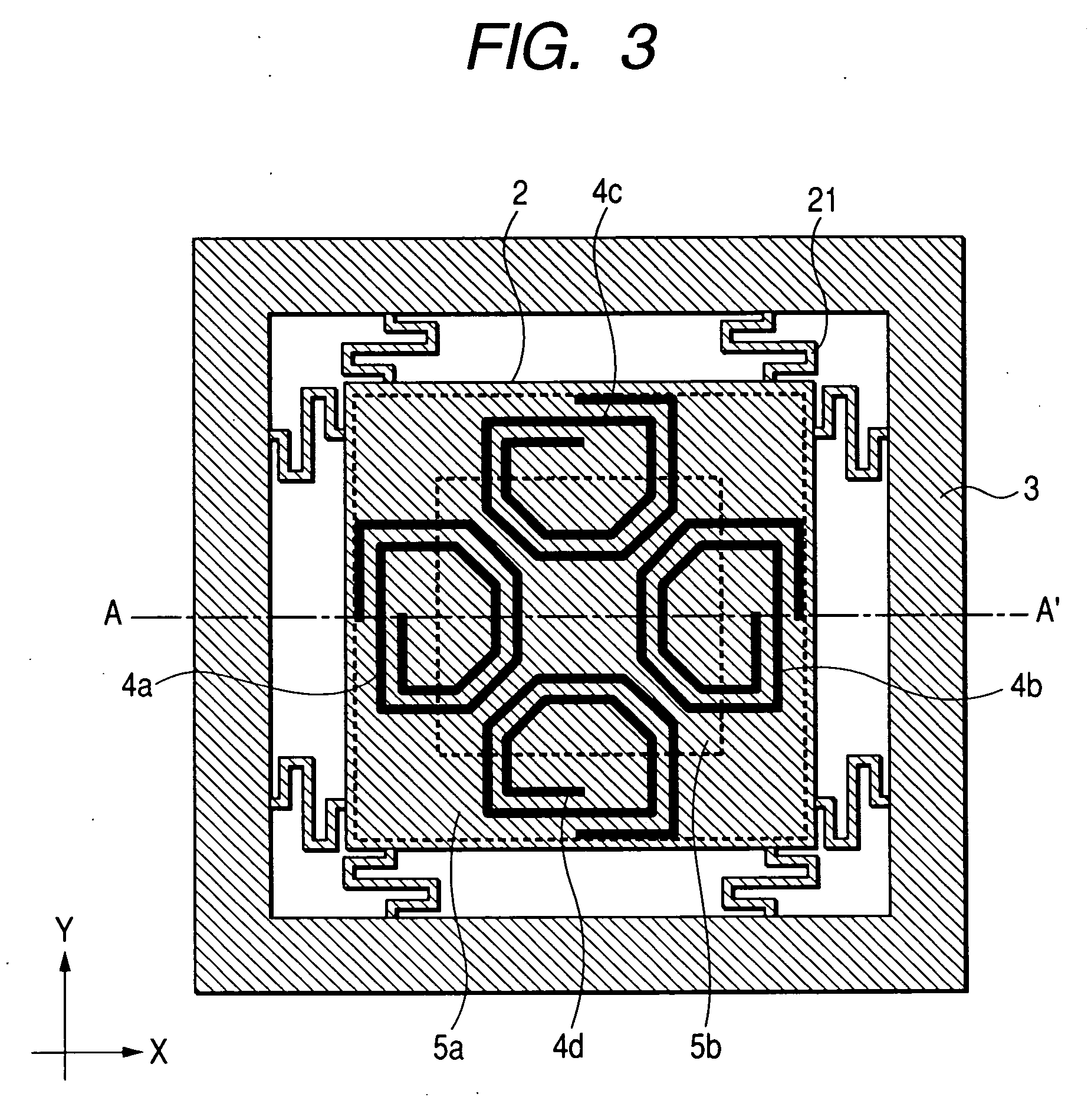
[0058] First, one example of a structure of the probe memory device according to this embodiment will be explained with reference to FIG. 1. The probe memory device of this first embodiment consists of, for example, a probe array chip 1, a stage scanner 2, a package 3, patterned coils 4, permanent magnets 5, a plurality of probes 12, a recording medium 20, a beam 21, etc.

[0059] The probe array chip 1 on which the probe 12 is fixed to a stationary system, like as package 3. The inventors adopt an arrangement in which each of the probes 12 provided in the probe array chip 1 is driven individually in the Z direction, and the stage scanner 2 carrying the recording medium 20 is driven in X and Y directions by the X-Y electromagnetic actuator. The high-stiffness elastic support structure supports the stage scanner 2 carryin...

second embodiment

[0104]FIG. 11 shows a structure of an X-Y electrostatic actuator that drives a stage scanner carrying a recording medium in the X and Y directions independently and cyclically, as a second embodiment of this invention.

[0105]FIG. 11A is a plan view of the electrostatic actuator for driving the stage scanner carrying a recording medium in the X and Y directions. The electrostatic actuator consists of a stage scanner 1103 supported by a base frame 1101 through a beam 1102. Although not illustrated in the figure, the recording medium is mounted on the stage scanner 1103 and there exists a probe for reading / writing data signal so that it accumulates over the recording medium in the Z direction. FIG. 11B is a sectional view in the cutting plane B-B′ in FIG. 11A, showing a positional relationship between an upper electrode 1104 installed on the rear side of the stage scanner 1103 and a lower electrode 1105 installed in the base frame 1101.

[0106] The upper electrode 1104 and the lower ele...

third embodiment

[0110] A different third embodiment of a stage scanner carrying a recording medium and a beam structure for the X-Y actuator of the probe memory device in the first and second embodiments will be described using FIG. 12.

[0111]FIG. 12 is a plan view of an actuator for driving a stage scanner in the X and Y directions in this third embodiment. The actuator according to this third embodiment consists of an inner frame 1203 supported by a base frame 1201 through a beam (X) 1202 in the X direction and a stage scanner supported by the inner frame 1203 through a beam (Y) 1204 in the Y direction.

[0112] When a stage scanner 1205 carrying a recording medium receives a driving force in the X direction by an unillustrated driving mechanism, the inner frame 1203, the beam (Y) 1204 supported in its interior, and the stage scanner 1205 are moved in the X direction as a single piece. At this time, since the beam (X) 1202 is designed to have a structure easy to expand and contract only in the X di...


PUM


Abstract

In a probe memory device, a technique of realizing consistency of high-density recording and high-speed reading/writing is provided. A recording medium is placed to a probe array chip on which a plurality of probes are arranged in such a way as to maintain a constant spacing thereto by adopting a high-stiffness elastic support structure. The recording medium is equipped with a stage scanner that is driven continuously while drawing a constant trajectory on an X-Y plane almost in parallel to a probe array chip plane. The probes are equipped with respective actuators each being driven in a Z direction almost perpendicular to the X-Y plane. Each of the probes is made to write or read by altering a distance between the probe and the recording medium in parallel processing. The X-Y actuator is controlled so that the probe may continue a predetermined cyclic movement. Moreover, a tracking area is provided in a portion of the recording medium, and a trajectory of the probe by actuation is controlled so as to have a fixed geometry.

Description

CLAIM OF PRIORITY [0001] The present application claims priority from Japanese application JP 2005-228319 filed on Aug. 5, 2005, the content of which is hereby incorporated by reference into this application. FIELD OF THE INVENTION [0002] This invention relates to a probe memory device and a positioning method therefor, and more specifically to an effective technique applied to X-Y stage scanner actuation that is used for an information recording device capable of writing or reading a large volume of electronic data with ultra-high density. BACKGROUND OF THE INVENTION [0003] As a technique that this inventor examined, for example, the following technique is conceivable in the probe memory device. [0004] The probe memory technique of using the principle of the scanning probe microscope is being expected as a recording method for increasing recording density. This technique is implemented with a recording medium, an actuator that places the recording medium on a stage scanner and actu...

Claims


Application Information

Patent Timeline
IPC IPC(8): G11B9/00
CPCG11B9/1436B82Y10/00
Inventor HASEBE, TAKEHIKOGOTO, YASUSHIYAMANAKA, KIYOKO
Owner HITACHI LTD
Why Eureka
Try Eureka