Diaphragm and silicon condenser microphone using same

Inactive Publication Date: 2011-09-29
AAC ACOUSTIC TECH (SHENZHEN) CO LTD +1
View PDF5 Cites 8 Cited by
  • Summary
  • Abstract
  • Description
  • Claims
  • Application Information

AI Technical Summary

Benefits of technology

[0013]In summary, the diaphragm is two-piece type and the vibrating member is connected with the substrate by the supporting members, thereby reducing restriction at the periphery of the vibration diaphragm. Moreover, each supporting member defines at least one slit, thereby preventing the deflection of the diaphragm, so that the product sensitivity can be effectively improved.

Problems solved by technology

However, the related silicon condenser microphone increases the restriction at the periphery of the vibrating diaphragm.

Method used


Image

  • Diaphragm and silicon condenser microphone using same
  • Diaphragm and silicon condenser microphone using same

Examples


Embodiment Construction

[0007]Reference will now be made to describe the exemplary embodiment of the present invention in detail.

[0008]An exemplary embodiment of the present invention provides a silicon condenser microphone used in a mobile phone for converting sound waves into electrical signals.

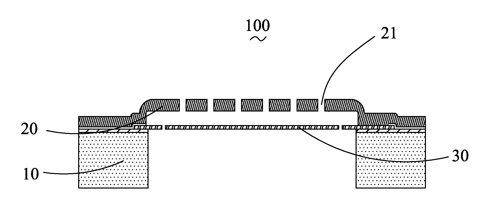
[0009]Referring to FIG. 1, a silicon condenser microphone 100 of the exemplary embodiment includes a substrate 10, a diaphragm 30 anchored to the substrate 10, and a backplate 20 opposed from the diaphragm 30. The backplate 20 defines a plurality of perforations 21 therethrough. The diaphragm 30 and the backplate 20 are respectively provided with an electrode (not shown) for cooperatively forming a capacitor. While the diaphragm 30 is activated to vibrate by the sound pressure of the sound waves, a distance between the diaphragm 30 and the backplate 20 is changed and the capacitance value of the capacitor is accordingly changed, which converts the sound waves into electrical signals.

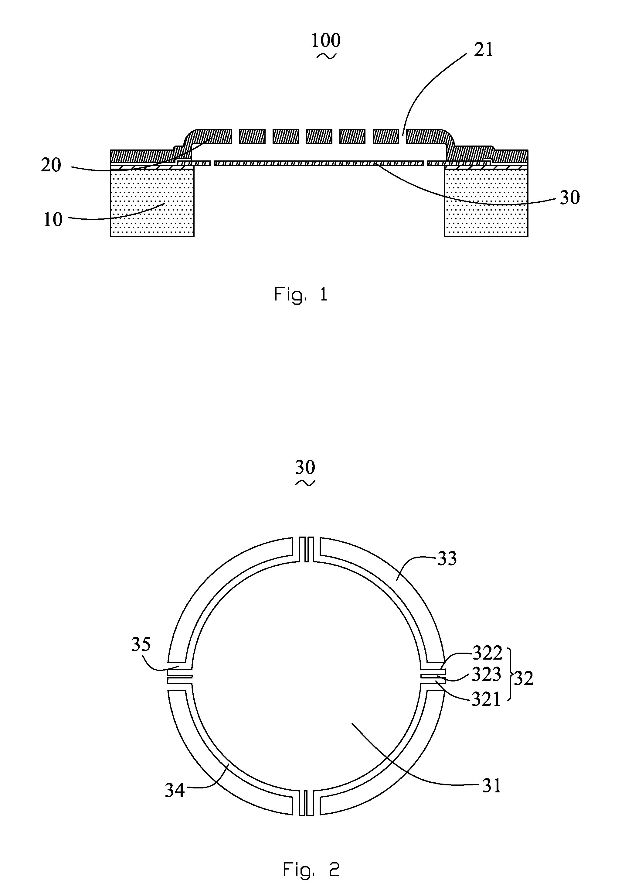
[0010]Referring to FIG. 2, the ...


PUM


Abstract

Disclosed is a diaphragm includes a vibrating member, a plurality of supporting members extending from a periphery of the vibrating member along a direction away from a center of the diaphragm, and a plurality of separating portions each located between two adjacent supporting members. Each of the supporting members defines a first beam, a second beam, and at least one slit between the first and second beams.

Description

FIELD OF THE INVENTION[0001]The present invention relates to MEMS (micro-electro-mechanical system) components, and more particularly, to a silicon condenser microphone having a diaphragm.DESCRIPTION OF RELATED ART[0002]Silicon condenser microphones are widely used in mobile phones to receive and convert sound waves into electrical signals. A silicon condenser microphone related to the present invention comprises a silicon substrate, a diaphragm arranged on the substrate and a backplate parallel and opposed from the diaphragm for forming a capacitor. The diaphragm is generally the type of one-piece and the entire periphery of the diaphragm is fixed on the substrate.[0003]However, the related silicon condenser microphone increases the restriction at the periphery of the vibrating diaphragm. In addition, when the diaphragm vibrates, a parasitic capacitor will occur between the diaphragm and the silicon substrate.[0004]So, it is necessary to provide a new means for solving the problems...

Claims


Application Information

Patent Timeline
IPC IPC(8): H04R11/04H04R7/00
CPCH04R19/04
Inventor YANG, BINZHANG, RUI
Owner AAC ACOUSTIC TECH (SHENZHEN) CO LTD
Why Eureka
Try Eureka