Audio radiation type reflective sound box structure

a sound box and radiation technology, applied in the direction of transducer details, electrical transducers, electrical apparatus, etc., can solve the problems of limited performance of speakers in the speaker box, relatively high directivity of speakers, and the ability to hear clear sounds, so as to achieve the effect of substantially lowering the directivity of the sound generated by the sound box structur

Active Publication Date: 2011-09-29
WANG CHAO LANG
View PDF31 Cites 38 Cited by
  • Summary
  • Abstract
  • Description
  • Claims
  • Application Information

AI Technical Summary

Benefits of technology

[0008]A primary object of the present invention is to provide an audio radiation type reflective sound box structure, which comprises a box, a hollow cone tube and at least one speaker. The box is provided with an opening on an upper portion thereof and a receiving space therein. The hollow cone tube has a first end received in the receiving space and a second end extended out of the opening, while a predetermined distance is defined between an inner side surface of the box and an outer side surface of the hollow cone tube, so as to form an airflow guiding space between the box and the hollow cone tube. The hollow cone tube is further formed with at least one vent adjacent to the first end and a speaker mounting hole extended inward from an inner side edge of the second end. The speaker is installed and mounted on the speaker mounting hole, and received in the hollow cone tube, so that the opening, the airflow guiding space, the vent and the speaker mounting hole can be communicated with each other. The second end of the hollow cone tube has an outer side edge extended outward to form an inclined side wall, wherein a first guiding angle is included between an outer edge tangent line of the inclined side wall and a central line of the hollow cone tube, while a predetermined gap is defined between an outer edge of the second end of the hollow cone tube and an edge of the opening of the box. Therefore, when a diaphragm of the speaker generates vibrations, compressed air in the hollow cone tube is pushed out of the opening through the vent and the airflow guiding space, and passed through the gap to collide with the outer edge of the inclined side wall, followed by being diffused toward a peripheral direction adjacent to a front side of the speaker along an extension direction of the inclined side wall. Thus, the sound box structure allows the speaker to precisely and directly generate sounds in the front side of the speaker, while the sounds reflected in the box can be evenly transmitted to a peripheral environment adjacent to the front side of the speaker through the first guiding angle of the inclined side wall and the gap between the outer edge of the second end of the hollow cone tube and the edge of the opening of the box. As a result, the directivity of the sounds generated by the sound box structure can be substantially lowered, so that users located both at the front side and in the peripheral environment of the speaker of the sound box structure can clearly hear the sounds played by the sound box structure.

Problems solved by technology

However, the performance of a speaker in the speaker box is limited to the reduced size of the speaker box, so that sounds played by the speaker have a relatively high directivity.
As a result, when users located at different positions use the speaker box installed in the electronic device and listen to sound played by the speaker box, only users located at a front side of the speaker box can clearly hear the sound, while users located otherwise are typically not enabled to hear clear sounds.
However, the box body 11 is limited to the inner design of the receiving space 110 and a planar panel on an edge of the one side thereof, so that sounds played by the sound box structure 1 have a relatively high directivity, resulting in limiting a speaker angle of the sounds.
Especially, high frequency sounds are seriously limited, so that users located at the periphery other than the front side of the sound box structure 1 can not clearly hear the high frequency sounds.

Method used


Image

  • Audio radiation type reflective sound box structure
  • Audio radiation type reflective sound box structure
  • Audio radiation type reflective sound box structure

Examples


Embodiment Construction

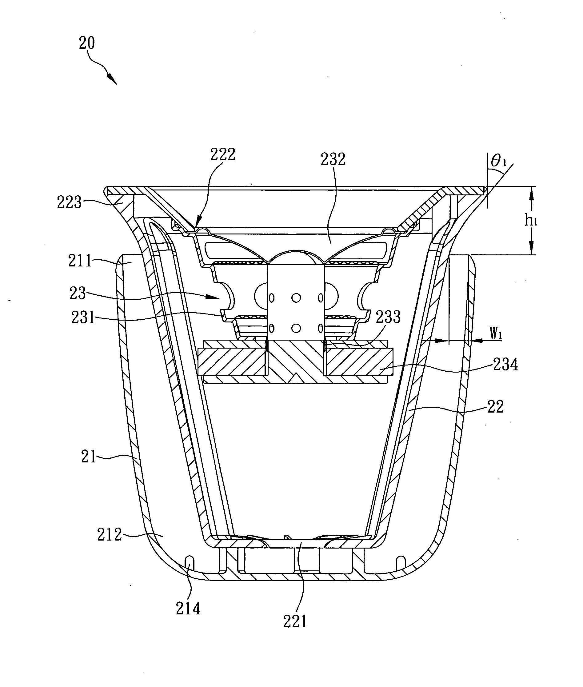
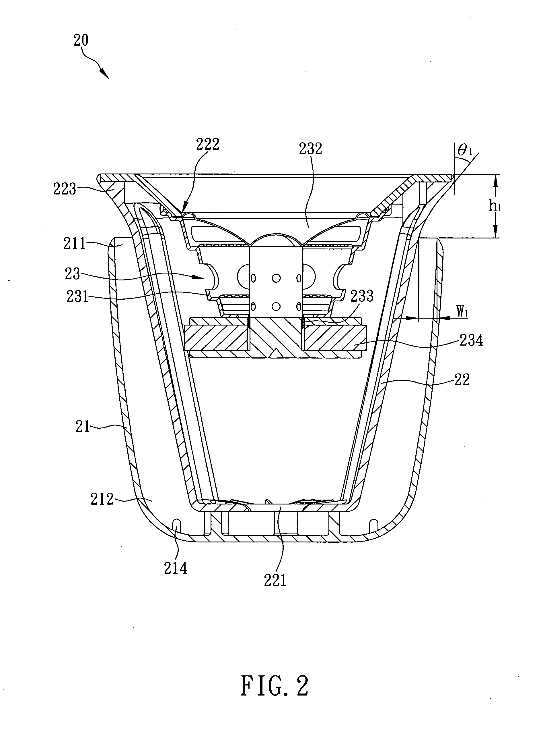
[0017]The present invention is an audio radiation type reflective sound box structure. Referring now to FIG. 2, a sound box structure designated by numeral 20 comprises a box 21, a hollow cone tube 22 and at least one speaker 23, wherein the box 21 is provided with an opening 211 on an upper portion thereof and a receiving space 212 therein. The hollow cone tube 22 has a first end received in the receiving space 212 and a second end extended out of the opening 211, while a predetermined distance W1 is defined between an inner side surface of the box 21 and an outer side surface of the hollow cone tube 22, so as to form an airflow guiding space (unlabeled) between the box 21 and the hollow cone tube 22. The hollow cone tube 22 is further formed with at least one vent 221 adjacent to the first end and a speaker mounting hole 222 extended inward from an inner side edge of the second end. Thus, the speaker 23 is installed and mounted on the speaker mounting hole 222, and received in the...


PUM


Abstract

The present invention is to provide an audio radiation type reflective sound box structure, which comprises a hollow cone tube having a first end received in a box, a second end extended out of an opening of the box to form an inclined side wall, and at least one vent disposed adjacent to the first end. When a diaphragm of a speaker mounted on an inner side edge of the second end generates vibrations, compressed air in the hollow cone tube is pushed out of the opening through the vent, and then collides with the outer edge of the inclined side wall and is diffused toward a peripheral direction adjacent to a front side of the speaker along an extension direction of the inclined side wall. Thus, the sounds reflected by the box can be evenly transmitted to a peripheral environment adjacent to the front side of the speaker.

Description

FIELD OF THE INVENTION[0001]The present invention relates to a sound box structure, more particularly to an audio radiation type reflective sound box structure comprising a hollow cone tube and a box, wherein the hollow cone tube has a first end received in a receiving space of the box, a second end extended out of an opening of the box to form an inclined side wall, at least one vent adjacent to the first end, and a speaker mounted on an inner side edge of the second end. When a diaphragm of the speaker generates vibrations, compressed air in the hollow cone tube is pushed out of the opening through the vent, and then collides with the outer edge of the inclined side wall and is diffused toward a peripheral direction adjacent to a. front side of the speaker along an extension direction of the inclined side wall. Thus, the sounds reflected by the box can be evenly transmitted to a peripheral environment adjacent to the front side of the speaker, so that users located both at the fro...

Claims


Application Information

Patent Timeline
Patent Type & Authority Applications(United States)
IPC IPC(8): H04R1/02
CPCH04R1/028H04R1/345H04R1/26
Inventor WANG, CHAO-LANG
Owner WANG CHAO LANG
Why Eureka
Try Eureka