
Antenna device and mobile device

a mobile device and antenna technology, applied in the direction of resonant antennas, elongated active elements, substation equipment, etc., can solve the problems of difficult to satisfy both of them in the radio frequency (rf) band used for communication, problems in stable material procurement and cost, etc., to achieve high optical transparency, avoid adversely affecting the radiation characteristic of the antenna, and achieve high degree of freedom in design creativity

Inactive Publication Date: 2011-09-29
SONY CORP
View PDF7 Cites 17 Cited by
  • Summary
  • Abstract
  • Description
  • Claims
  • Application Information

AI Technical Summary

Benefits of technology

[0012]The present invention has been made in such a background. It is desirable to provide an antenna device including an antenna element to be fed and having optical transparency without deteriorating a radiation characteristic of the antenna at a relatively low price.
[0033]The above-described mobile device is, for example a mobile telephone terminal. At the time of receiving at least a telephone call or a mail of the mobile telephone terminal, the light emitting section displays an icon, a symbol, or a character with lighting in order to inform the reception. In the light emitting display, the mesh part of the antenna element has optical transparency, and thus there is no problem.
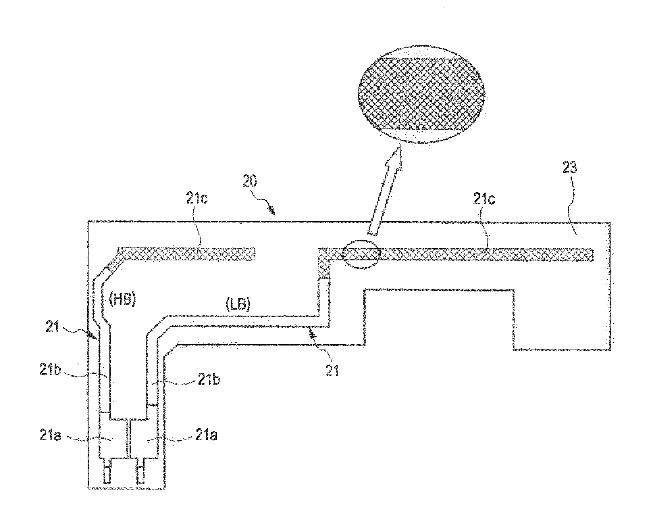
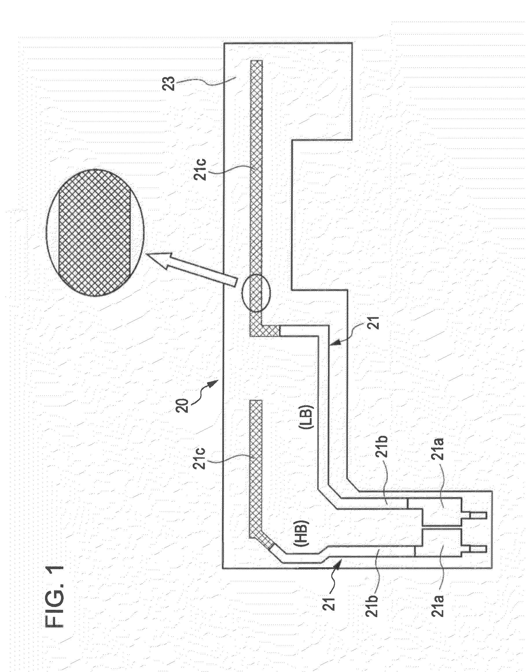
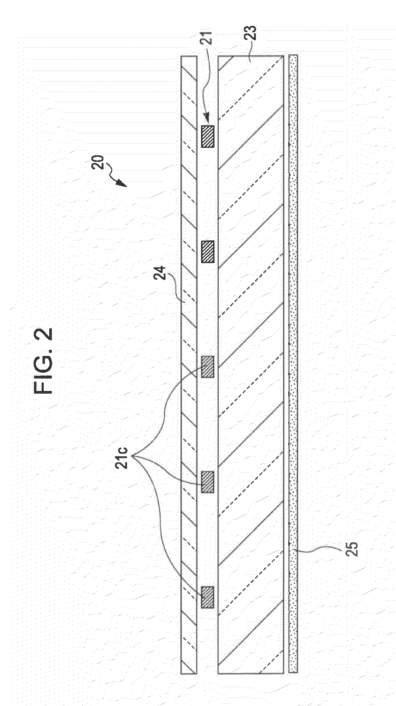
[0034]By the present invention, at least a part of the area of the antenna element is formed in a mesh state, and the feeding part and an area in the vicinity thereof are of a finer mesh or solid. Thus, it is possible to obtain optical transparency without adversely affecting the radiation characteristic of the antenna. As a result, in a mobile device using the antenna device, it becomes possible to achieve high optical transparency in the antenna element section, and to give high degree of freedom in design creativity.

Problems solved by technology

It is therefore difficult to satisfy both of them in a radio frequency (RF) band used for communication.
Also, since a rare metal, indium, is used, there are problems in stable procurement of the material and in its cost.
However, this is only for the case of using an antenna as a reflector, and not for the case of an antenna configuration in which a mesh part itself is used as a primary radiator to be fed.

Method used


Image

  • Antenna device and mobile device
  • Antenna device and mobile device
  • Antenna device and mobile device

Examples


Embodiment Construction

[0048]In the following, detailed descriptions will be given of preferred embodiments of the present invention with reference to the drawings.

[0049]FIG. 1 is a diagram illustrating a schematic configuration of an antenna device according to an embodiment of the present invention. The antenna device includes a flexible printed circuit (FPC) 20 as a flexible part. In this embodiment, two conductive patterns for a high band (HB) and a low band (LB) are formed on the flexible printed circuit 20 on a transparent plate 23 as antenna elements 21 that are fed as primary radiators. In this example, a multiband linear antenna corresponding to a plurality of frequency bands is taken as an example. For multiband, for example, an 800-MHz band and 1950 MHz for a cellular phone, and 2.5 GHz for Bluetooth (registered trademark), etc., are considered.

[0050]Both of the antenna elements 21 have a gold-plated contact point 21a, which is a feeding part to be fed, and a non-mesh part 21b following to the ...


PUM


Abstract

An antenna element including a feeding part and a mesh part including at least a part of an area formed in a mesh state. The feeding part and an area of the antenna element in close proximity to the mesh part are formed of a finer mesh than the mesh part or formed of a solid.

Description

CROSS REFERENCE TO RELATED APPLICATION[0001]This application claims the benefit of priority of Provisional Application Ser. No. 61 / 317,307, filed Mar. 25, 2010, the entire contents of which is incorporated herein by reference.BACKGROUND OF THE INVENTION[0002]1. Field of the Invention[0003]The present invention relates to an antenna device including an antenna element to be fed and to a mobile device including the antenna device.[0004]2. Description of the Related Art[0005]To date, a radio-communication antenna has become an indispensable part of a mobile device, such as a mobile telephone terminal, etc. In general, a part of an antenna sometimes disadvantageously protrudes from a housing of a device because it is necessary to ensure an electric characteristic (radiation characteristic) of the antenna. Also, in the case of a built-in antenna, the antenna occupies a substantial area inside a housing, and thus unfortunately the device becomes physically large in size.[0006]In order to ...

Claims


Application Information

Patent Timeline
IPC IPC(8): H04M1/00H01Q1/36H01Q21/00H01Q1/06H01Q21/30
CPCH01Q1/243H01Q9/42H01Q9/40
Inventor SHOJI, HIDEAKIKANAYAMA, YOSHIKI
Owner SONY CORP
Learn More