Wave gear device having three-dimensionally contactable shifted tooth profile

Active Publication Date: 2011-09-29
HARMONIC DRIVE SYST IND CO LTD
View PDF22 Cites 19 Cited by
  • Summary
  • Abstract
  • Description
  • Claims
  • Application Information

AI Technical Summary

Benefits of technology

[0034]In the wave gear device of the present invention, the flexible externally toothed gear is shifted in the tooth trace direction while taking into account the coning thereof, and the moving locus of the teeth of the flexible externally toothed gear in the principal section relative to the teeth of the rigid internally toothed gear is designed so as to share a bottom with the moving locus of other sections, thereby achieving a reasonable meshing engagement through the entire tooth trace in addition to the regular wide-range meshing engagement in the principa

Problems solved by technology

The degree to which methods for setting a reasonable tooth profile account for such deflecting action

Method used


Image

  • Wave gear device having three-dimensionally contactable shifted tooth profile
  • Wave gear device having three-dimensionally contactable shifted tooth profile
  • Wave gear device having three-dimensionally contactable shifted tooth profile

Examples


Embodiment Construction

[0046]A wave gear device in which the present invention is applied is described hereinbelow with reference to the drawings.

[0047](Configuration of Wave Gear Device)

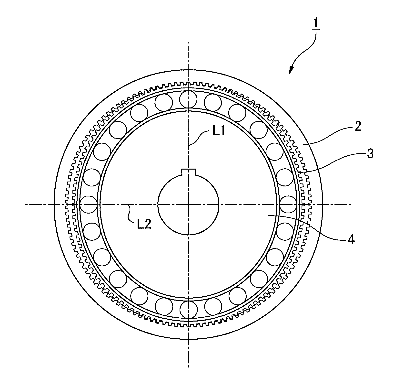
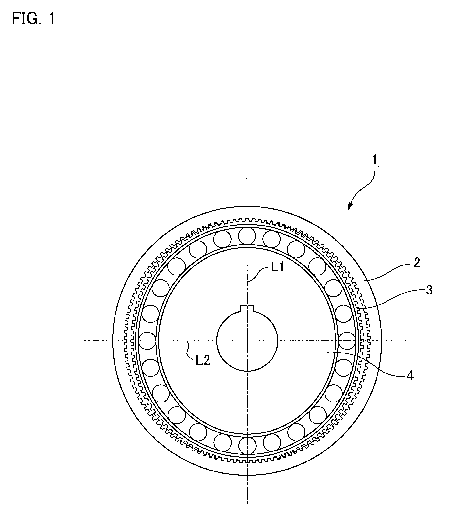
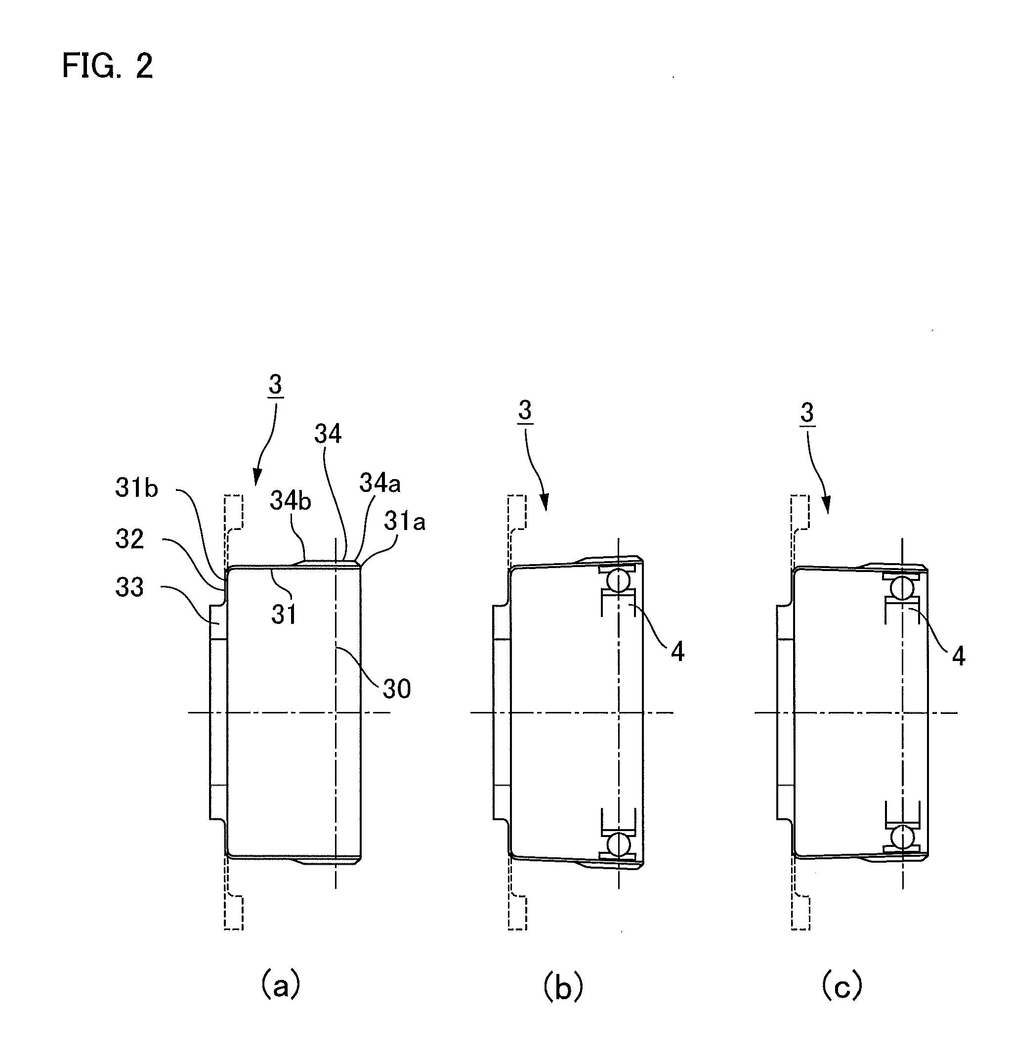
[0048]FIG. 1 is a front view of a wave gear device as an object of the present invention, and FIGS. 2(a) through (c) are cross-sectional views showing cross sections, including axes, of a state in which the opening of the flexible externally toothed gear has been deflected into an ellipsoidal shape, wherein FIG. 2(a) shows a state before deformation, FIG. 2(b) shows a cross section including the major axis of the ellipse after deformation, and FIG. 2(c) shows a cross section including the minor axis of the ellipse after deformation. In FIGS. 2(a) through (c), the solid lines show the cup-shaped flexible externally toothed gear, and the dashed lines show a silk-hat shaped flexible externally toothed gear.

[0049]As shown in these drawings, a wave gear device 1 has a circular rigid internally toothed gear 2, a flexible extern...


PUM


Abstract

Disclosed is a wave gear device (1) for setting the flexible state of the principal section (30) of a flexible external gear in a normal-deflection state (at a deflection coefficient κ=1). The moving locus of a tooth profile in the principal section (30) is determined by a rack approximation, and a similar curve (BC), which is obtained by similarly transforming a curve (AB) cut from that moving locus, is used to define the fundamental addendum shape of the tooth profile in the principal section. The portion of the tooth profile of the flexible external gear other than the principal section is shifted so that both each negative-deflection side moving locus (M3), which is obtained in each plane of rotation to deflect in a negative deflection state (at the deflection coefficient κ<1) closer to the diaphragm side than the principal section and each positive-deflection side moving locus (M2), which is obtained in each plane of rotation to deflect in a positive deflection state (at the deflection coefficient κ>1) closer to the front end opening side than the principal section, may become curves (M3a and M2a) to contact at the bottom (a point (P)) of a normal-deflection moving locus (M1). The partial meshing engagement can also be held at the section other than the principal section in the tooth trace direction, so that the load torque performance of the wave gear device can be advantageously improved.

Description

TECHNICAL FIELD [0001]The present invention relates to the improvement of a tooth profile of a rigid internally toothed gear and a flexible externally toothed gear in a wave gear device. More specifically, the present invention relates to a shape of a tooth whereby the gears of the wave gear device can maintain a meshing engagement over a wide range in a principal section (plane of rotation) set at a predetermined position in a tooth trace direction, while a partial meshing engagement can also be held in another plane of rotation in the tooth trace direction.BACKGROUND ART[0002]Since the invention (Patent Document 1) of the originator C. W. Musser, various inventions of wave gear devices have been proposed up to the present by many researchers, beginning with Musser himself and including the present inventors. There are also various inventions relating merely to the tooth profiles of these devices. For example, in Patent Document 2, the present inventors propose that the fundamental...

Claims


Application Information

Patent Timeline
IPC IPC(8): F16H1/32
CPCF16H2049/003F16H55/0833Y10T74/19
Inventor ISHIKAWA, SHOICHI
Owner HARMONIC DRIVE SYST IND CO LTD
Why Eureka
Try Eureka